Toyota Venza: Parts Location
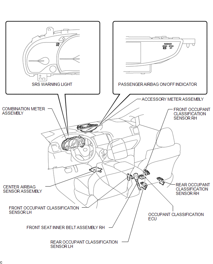
PARTS LOCATION
ILLUSTRATION
 Precaution
PRECAUTION
1. PRECAUTION FOR DISCONNECTING THE BATTERY CABLE
NOTICE:
When disconnecting the cable from the negative (-) battery terminal, initialize
the following systems after the cable is recon ...
 System Diagram
SYSTEM DIAGRAM
...
Other materials about Toyota Venza:
Replacement
REPLACEMENT
PROCEDURE
1. REPLACE GENERATOR DRIVE END FRAME BEARING
(a) Remove the 4 screws and bearing retainer from the drive end frame.
(b) Using SST and a hammer, tap out the drive end ...
Inspection
INSPECTION
PROCEDURE
1. INSPECT COMPRESSOR WITH PULLEY (SOLENOID VALVE)
(a) Measure the resistance according to the value(s) in the table below.
Standard Resistance:
Tester Connection
Condition
...
How To Proceed With Troubleshooting
HOW TO PROCEED WITH TROUBLESHOOTING
1. OPERATION FLOW
HINT:
Perform troubleshooting in accordance with the procedure below. The following
is an outline of basic troubleshooting procedure. Confirm the troubleshooting procedure
for the circuit you are wor ...

0.1232