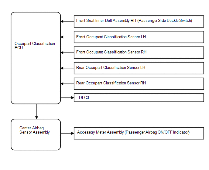
Toyota Venza: System Diagram
SYSTEM DIAGRAM
 Parts Location
PARTS LOCATION
ILLUSTRATION
...
 How To Proceed With Troubleshooting
CAUTION / NOTICE / HINT
HINT:
*: Use the Techstream
PROCEDURE
1.
VEHICLE BROUGHT TO WORKSHOP
NEXT
...
Other materials about Toyota Venza:
Intake Air Control Valve Actuator(for Tcv)
Components
COMPONENTS
ILLUSTRATION
Removal
REMOVAL
PROCEDURE
1. REMOVE INTAKE MANIFOLD
(a) Remove the intake manifold (See page ).
2. REMOVE INTAKE AIR CONTROL VALVE ACTUATOR (for TCV)
(a) Remove the 2 bolts, intake air control valve actuator a ...
System Diagram
SYSTEM DIAGRAM
Communication Table
Sender
Receiver
Signal
Communication Line
A/C amplifier
ECM
Magnetic clutch request signal*1
CAN
Idle up reques ...
Brake Pedal Load Sensing Switch (C1267/67)
DESCRIPTION
The brake pedal load sensing switch is turned on when the brake pedal is depressed
with force exceeding a predetermined level.
The skid control ECU detects if the brake pedal is depressed or not via this
circuit.
DTC Code
...

0.1361