Toyota Venza: Automatic High Beam Mirror (B124A)
DESCRIPTION
The DTC is stored when the main body ECU (driver side junction block assembly) detects malfunctions in the inner rear view mirror assembly.
|
DTC No. |
DTC Detection Condition |
Trouble Area |
|---|---|---|
|
B124A |
Malfunction in inner rear view mirror assembly |
Inner rear view mirror assembly |
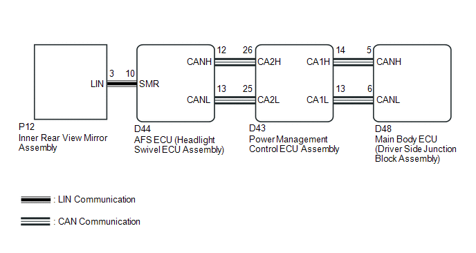
WIRING DIAGRAM
CAUTION / NOTICE / HINT
NOTICE:
First perform the communication function inspections in How to Proceed with Troubleshooting to confirm that there are no CAN communication malfunctions before troubleshooting this symptom.
PROCEDURE
|
1. |
CHECK FOR DTC |
(a) Clear the DTCs (See page .gif) ).
).
(b) Check for DTCs (See page ).
OK:
DTC B124A is not output.
| OK | .gif) |
USE SIMULATION METHOD TO CHECK |
| NG | |
REPLACE INNER REAR VIEW MIRROR ASSEMBLY |
 Lost Communication with ECM (U0101,U0073,U0126,U0129,U0142,U0182,U1000)
DESCRIPTION
The DTCs are stored when the CAN communication system is malfunctioning.
DTC No.
DTC Detection Condition
Trouble Area
U0101
L ...
 Automatic High Beam System (B124B)
DESCRIPTION
The DTC is stored when the main body ECU (driver side junction block assembly)
detects malfunctions in the automatic high beam system.
DTC No.
DTC Detection Condi ...
Other materials about Toyota Venza:
ECM / PCM Internal Engine Off Timer Performance (P2610)
DTC SUMMARY
DTC No.
Monitoring Item
Malfunction Detection Condition
Trouble Area
Detection Timing
Detection Logic
P2610
Soak timer (built into ECM)
An ECM ...
How To Proceed With Troubleshooting
CAUTION / NOTICE / HINT
HINT:
Use the following procedures to troubleshoot the tire pressure warning
system.
*: Use the Techstream.
PROCEDURE
1.
VEHICLE BROUGHT TO WORKSHOP
NEXT
...
Data List / Active Test
DATA LIST / ACTIVE TEST
1. DATA LIST
HINT:
Using the Techstream to read the Data List allows the values or states of switches,
sensors, actuators and other items to be read without removing any parts. This non-intrusive
inspection can be very useful bec ...

0.1506