Toyota Venza: Parts Location
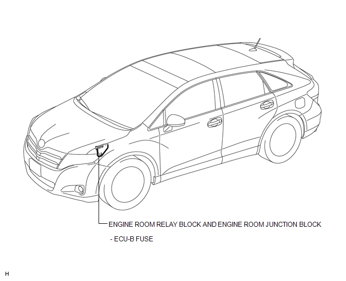
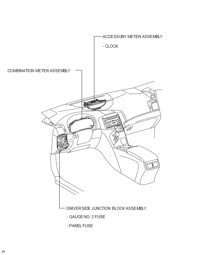
PARTS LOCATION
ILLUSTRATION
ILLUSTRATION
 Clock System
...
 System Diagram
SYSTEM DIAGRAM
1. CAN AND DIRECT LINE SIGNALS
2. INPUT AND OUTPUT SIGNALS OF THE ACCESSORY METER ASSEMBLY
Warning light or indicator light
Communication Signal
Re ...
Other materials about Toyota Venza:
Navigation Receiver Assembly Communication Stop Mode
DESCRIPTION
Detection Item
Symptom
Trouble Area
Navigation Receiver Assembly Communication Stop Mode
"Display and Navigation (AVN1)" is not displayed on the "CAN
Bus ...
Inspection
INSPECTION
PROCEDURE
1. INSPECT COMPRESSOR WITH PULLEY (SOLENOID VALVE)
(a) Measure the resistance according to the value(s) in the table below.
Standard Resistance:
Tester Connection
Condition
...
Installation
INSTALLATION
PROCEDURE
1. INSTALL THROTTLE BODY ASSEMBLY
(a) Install a new gasket to the intake manifold.
(b) Install the fuel tube bracket with the bolt.
Torque:
7.5 N·m {76 kgf ...

0.1381