Toyota Venza: System Diagram
SYSTEM DIAGRAM
1. CAN AND DIRECT LINE SIGNALS
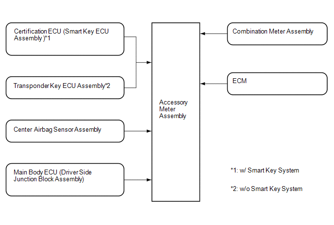
2. INPUT AND OUTPUT SIGNALS OF THE ACCESSORY METER ASSEMBLY
|
Warning light or indicator light |
Communication Signal |
Receiver |
Communication Line |
Sender |
|---|---|---|---|---|
|
Front passenger side seat belt warning light |
Front passenger side seat belt warning light |
Accessory Meter Assembly |
Direct Line |
Combination Meter Assembly |
|
Tire pressure warning light |
Tire pressure warning light |
Accessory Meter Assembly |
Direct Line |
Combination Meter Assembly |
|
AWD warning light*1 |
AWD warning light |
Accessory Meter Assembly |
Direct Line |
Combination Meter Assembly |
|
Slip indicator light |
Slip indicator light |
Accessory Meter Assembly |
Direct Line |
Combination Meter Assembly |
|
VSC OFF indicator light |
VSC OFF indicator light |
Accessory Meter Assembly |
Direct Line |
Combination Meter Assembly |
|
EPS warning light |
EPS warning light |
Accessory Meter Assembly |
Direct Line |
Combination Meter Assembly |
|
Washer level warning light |
Washer level warning light |
Accessory Meter Assembly |
Direct Line |
Combination Meter Assembly |
|
TRAC OFF indicator light |
TRAC OFF indicator light |
Accessory Meter Assembly |
Direct Line |
Combination Meter Assembly |
|
Security indicator light |
Security indicator light |
Accessory Meter Assembly |
Direct Line |
Transponder Key ECU Assembly*2 |
|
Certification ECU (Smart Key ECU Assembly)*3 |
||||
|
Key indicator light*3 |
Key indicator light |
Accessory Meter Assembly |
Direct Line |
Certification ECU (Smart Key ECU Assembly) |
|
Passenger airbag ON/OFF indicator light |
Passenger airbag ON/OFF indicator light |
Accessory Meter Assembly |
Direct Line |
Center Airbag Sensor Assembly |
|
MIL (Check engine warning light) |
MIL (Check engine warning light) |
Accessory Meter Assembly |
Direct Line |
ECM |
|
Cruise information display |
Cruise information display |
Accessory Meter Assembly |
Direct Line |
Combination Meter Assembly |
|
Air conditioning display |
Air conditioning display |
Accessory Meter Assembly |
Direct Line |
Combination Meter Assembly |
|
Each system warning display*4 |
Each system warning |
Accessory Meter Assembly |
Direct Line |
Combination Meter Assembly |
|
Each system customize display |
Each system customize |
Accessory Meter Assembly |
Direct Line |
Combination Meter Assembly |
|
DTC (Diagnostic Trouble Code) display |
DTC display |
Accessory Meter Assembly |
Direct Line |
Combination Meter Assembly |
- *1: for AWD
- *2: w/o Smart Key System
- *3: w/ Smart Key System
- *4: w/ Multi-information Display
 Parts Location
PARTS LOCATION
ILLUSTRATION
ILLUSTRATION
...
 How To Proceed With Troubleshooting
CAUTION / NOTICE / HINT
HINT:
Use the following procedure to troubleshoot.
PROCEDURE
1.
VEHICLE BROUGHT TO WORKSHOP
NEXT
...
Other materials about Toyota Venza:
Initialization
INITIALIZATION
1. RESET TRANSAXLE COMPENSATION CODE
NOTICE:
If the following parts have been replaced, initialize the TCM and perform
the following "Reset Memory" and "Perform Road Test to Allow TCM to learn"
steps.
- ...
Camshaft Position "B" - Timing Over-Advanced or System Performance (Bank 1)
(P0014,P0015)
DESCRIPTION
Refer to DTC P0013 (See page ).
DTC No.
DTC Detection Condition
Trouble Area
P0014
The valve timing is stuck at a certain value when in the advance range
(2 trip detection logic).
...
CD cannot be Ejected
PROCEDURE
1.
CHECK OPERATION
(a) Press the disc eject switch of the radio and display receiver assembly for
5 seconds or more and check that the CD is ejected.
OK:
CD is ejected.
NG
REPLACE RADIO AND D ...

0.1573