Toyota Venza: Back Door Closer Switch Malfunction (B2251)
DESCRIPTION
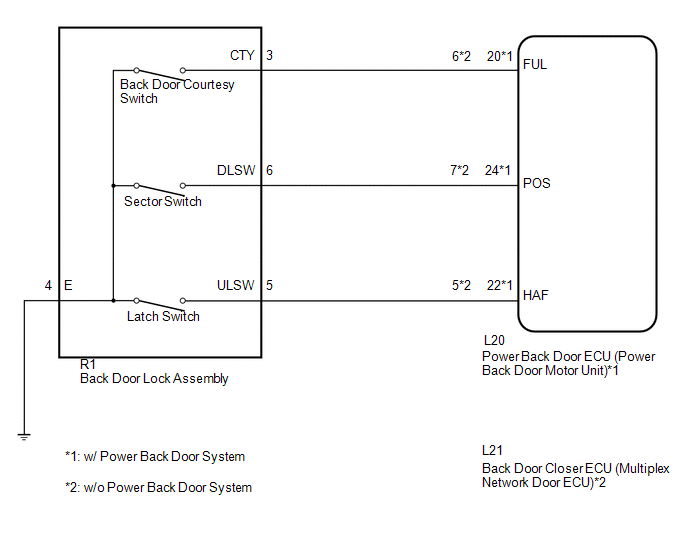
The power back door ECU (power back door motor unit)*1 or back door closer ECU (multiplex network door ECU)*2 receives signals from the latch switch, sector switch and back door courtesy switch, which are built into the back door lock. Based on these switch signals, the latch position of the back door lock is determined.
|
DTC No. |
DTC Detection Condition |
Trouble Area |
|---|---|---|
|
B2251 |
While the back door closer is operating, a malfunction is detected in position information from the back door courtesy switch within a specified amount of time. |
|
- *1: w/ Power Back Door System
- *2: w/o Power Back Door System
WIRING DIAGRAM
PROCEDURE
|
1. |
READ VALUE USING TECHSTREAM (BACK DOOR COURTESY SWITCH) |
(a) Connect the Techstream to the DLC3.
(b) Turn the ignition switch to ON.
(c) Turn the Techstream on.
(d) Enter the following menus: Body Electrical / Back Door / Data List.
(e) Check if the switch functions properly.
Back Door (Power Back Door ECU*1 or Back Door Closer ECU*2)|
Tester Display |
Measurement Item/Range |
Normal Condition |
Diagnostic Note |
|---|---|---|---|
|
Courtesy SW |
Back door courtesy switch signal / ON or OFF |
ON: Back door open OFF: Back door closed |
- |
- *1: w/ Power Back Door System
- *2: w/o Power Back Door System
OK:
The display is as specified in the normal condition column.
|
Result |
Proceed to |
|---|---|
|
NG |
A |
|
OK (w/ Power Back Door System) |
B |
|
OK (w/o Power Back Door System) |
C |
| B | .gif) |
REPLACE POWER BACK DOOR ECU (POWER BACK DOOR MOTOR UNIT) |
| C | |
REPLACE BACK DOOR CLOSER ECU (MULTIPLEX NETWORK DOOR ECU) |
|
.gif)
|
2. |
INSPECT BACK DOOR LOCK ASSEMBLY (BACK DOOR COURTESY SWITCH) |
(a) Remove the back door lock assembly (See page
.gif) ).
).
(b) Measure the resistance according to the value(s) in the table below.
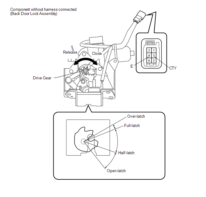
Standard Resistance:
Back Door Courtesy Switch|
Tester Connection |
Condition |
Specified Condition |
|---|---|---|
|
3 (CTY) - 4 (E) |
Open-latch |
Below 1 Ω |
|
3 (CTY) - 4 (E) |
Half-latch |
Below 1 Ω |
|
3 (CTY) - 4 (E) |
Full-latch |
10 kΩ or higher |
|
3 (CTY) - 4 (E) |
Over-latch |
10 kΩ or higher |
| NG | |
REPLACE BACK DOOR LOCK ASSEMBLY |
|
|
3. |
CHECK HARNESS AND CONNECTOR (BACK DOOR LOCK - POWER BACK DOOR ECU OR BACK DOOR CLOSER ECU) |
(a) w/ Power Back Door System
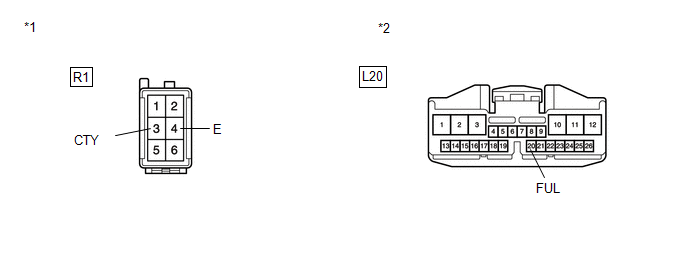
(1) Disconnect the R1 back door lock assembly connector and L20 power back door ECU connector.
(2) Measure the resistance according to the value(s) in the table below.
Standard Resistance:
|
Tester Connection |
Condition |
Specified Condition |
|---|---|---|
|
R1-3 (CTY) - L20-20 (FUL) |
Always |
Below 1 Ω |
|
R1-4 (E) - Body ground |
Always |
Below 1 Ω |
|
R1-3 (CTY) - Body ground |
Always |
10 kΩ or higher |
|
*1 |
Front view of wire harness connector (to Back Door Lock) |
|
*2 |
Front view of wire harness connector (to Power Back Door ECU) |
|
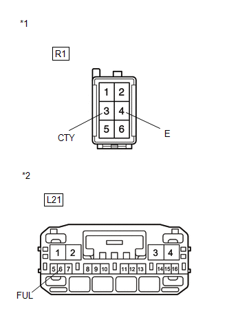
(b) w/o Power Back Door System (1) Disconnect the R1 back door lock assembly connector and L21 back door closer ECU connector. (2) Measure the resistance according to the value(s) in the table below. Standard Resistance:
|
|
|
Result |
Proceed to |
|---|---|
|
NG |
A |
|
OK (w/ Power Back Door System) |
B |
|
OK (w/o Power Back Door System) |
C |
| A | |
REPAIR OR REPLACE HARNESS OR CONNECTOR |
| B | |
REPLACE POWER BACK DOOR ECU (POWER BACK DOOR MOTOR UNIT) |
| C | |
REPLACE BACK DOOR CLOSER ECU (MULTIPLEX NETWORK DOOR ECU) |
 Data List / Active Test
DATA LIST / ACTIVE TEST
1. DATA LIST
HINT:
Using the Techstream to read the Data List allows the values or states of switches,
sensors, actuators and other items to be read without removing any p ...
 Diagnostic Trouble Code Chart
DIAGNOSTIC TROUBLE CODE CHART
HINT:
If a trouble code is displayed during the DTC check, inspect the trouble areas
listed for that code. For details of the code, refer to the following "See p ...
Other materials about Toyota Venza:
Open in Rear Floor Electrical Key Oscillator Circuit (B27A6)
DESCRIPTION
The certification ECU (smart key ECU assembly) generates a request signal and
sends it to the indoor electrical key oscillator (for center floor). To detect the
key inside the cabin, the indoor electrical key oscillator (for center floor) crea ...
Room Temperature Sensor Circuit (B1411/11)
DESCRIPTION
The room temperature sensor is installed in the instrument panel. It detects
the cabin temperature to control the air conditioning AUTO mode. The resistance
of the room temperature sensor changes in accordance with the cabin temperature.
As ...
Removal
REMOVAL
PROCEDURE
1. RECOVER REFRIGERANT FROM REFRIGERATION SYSTEM
2. DISCHARGE FUEL SYSTEM PRESSURE
3. PLACE FRONT WHEELS FACING STRAIGHT AHEAD
4. REMOVE FRONT WHEELS
5. DISCONNECT CABLE FROM NEGATIVE BATTERY TERMINAL
NOTICE:
When disconnecting ...

0.151