Toyota Venza: Parts Location
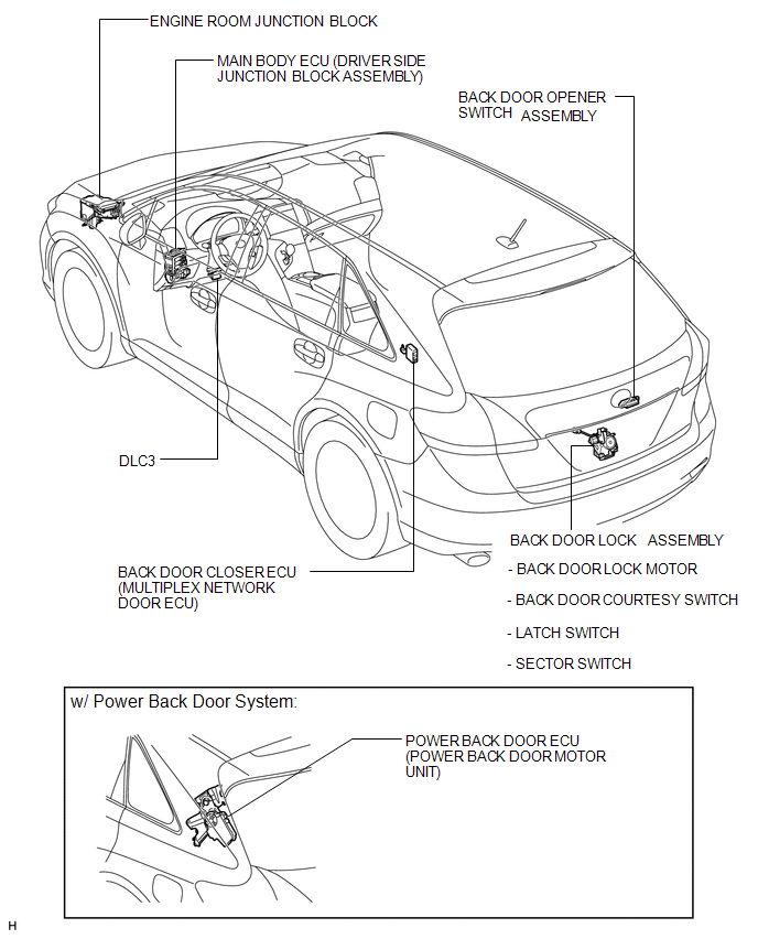
PARTS LOCATION
ILLUSTRATION
 Precaution
PRECAUTION
NOTICE:
When disconnecting the cable from the negative (-) battery terminal, initialize
the following systems after the cable is reconnected.
System Name
See Proc ...
 System Diagram
SYSTEM DIAGRAM
Communication Method
Transmitting ECU
Receiver
Signal
Communication Method
Main body ECU (Driver Side Junction Block Asse ...
Other materials about Toyota Venza:
Terminals Of Ecu
TERMINALS OF ECU
1. CHECK POSITION CONTROL ECU AND SWITCH ASSEMBLY
(a) Disconnect the T10 and T11 position control ECU and switch assembly connectors.
(b) Measure the voltage and resistance according to the value(s) in the table
below.
HINT:
Measure t ...
Diagnostic Trouble Code Chart
DIAGNOSTIC TROUBLE CODE CHART
If a trouble code is displayed during the DTC check, check the trouble areas
listed for that code in the table below and proceed to the appropriate page.
Cruise Control System
DTC Code
Detection Item
...
How To Proceed With Troubleshooting
CAUTION / NOTICE / HINT
HINT:
Perform troubleshooting in accordance with the following flowchart.
*: Use the Techstream.
PROCEDURE
1.
VEHICLE BROUGHT TO WORKSHOP
NEXT
...

0.1149