Toyota Venza: System Diagram
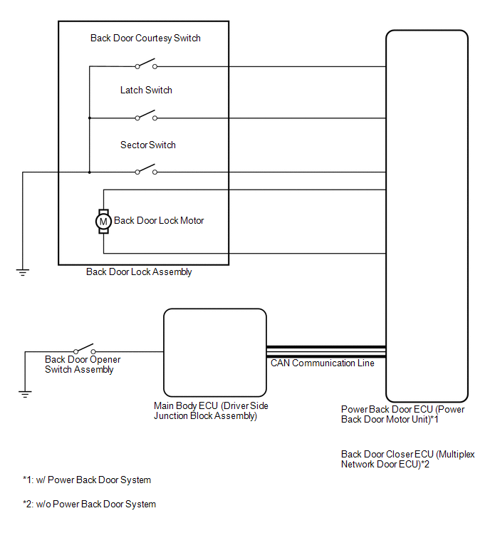
SYSTEM DIAGRAM
 Communication Method
|
Transmitting ECU |
Receiver |
Signal |
Communication Method |
|---|---|---|---|
|
Main body ECU (Driver Side Junction Block Assembly) |
Power back door ECU (Power back door motor unit)*1 Back door closer ECU (Multiplex network door ECU)*2 |
Back door opener switch signal |
CAN |
- *1: w/ Power Back Door System
- *2: w/o Power Back Door System
 Parts Location
PARTS LOCATION
ILLUSTRATION
...
 System Description
SYSTEM DESCRIPTION
1. BACK DOOR CLOSER SYSTEM DESCRIPTION
(a) Operating any power back door switch when the back door is fully closed inputs
a request signal to the power back door ECU*1 or back d ...
Other materials about Toyota Venza:
Removal
REMOVAL
PROCEDURE
1. DISCONNECT CABLE FROM NEGATIVE BATTERY TERMINAL
NOTICE:
When disconnecting the cable, some systems need to be initialized after the cable
is reconnected (See page ).
2. REMOVE REAR DOOR INSIDE HANDLE BEZEL PLUG
3. REMOVE REAR P ...
Precaution
PRECAUTION
1. PRECAUTION FOR DISCONNECTING CABLE FROM NEGATIVE BATTERY TERMINAL
NOTICE:
When disconnecting the cable from the negative (-) battery terminal, initialize
the following system after the terminal is reconnected:
System Name
...
Back Door Motor Clutch Malfunction (B2225)
DESCRIPTION
When an electrical malfunction (open or short) is detected in the clutch circuit
of the power back door ECU (power back door motor unit) while the power back door
is operating, the power back door ECU (power back door motor unit) stores DTC B2 ...

0.156