Toyota Venza: Outer Rear View Mirror Cover
Components
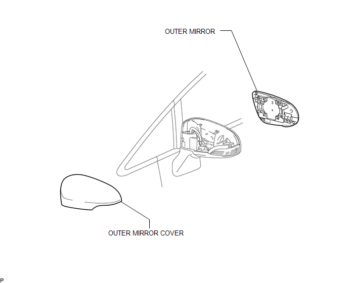
COMPONENTS
ILLUSTRATION
Installation
INSTALLATION
PROCEDURE
1. INSTALL OUTER MIRROR COVER
|
(a) Engage the 7 claws to install the outer mirror cover. |
|
2. INSTALL OUTER MIRROR
.gif)
Removal
REMOVAL
PROCEDURE
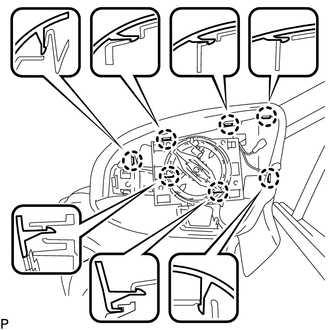
1. REMOVE OUTER MIRROR
.gif)
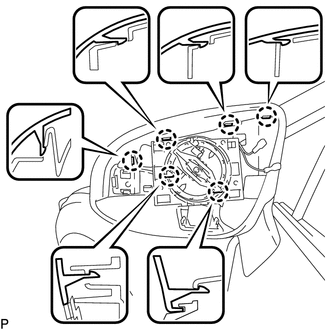
2. REMOVE OUTER MIRROR COVER
|
(a) Disengage the 6 claws. |
|
|
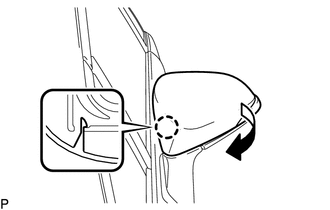
(b) Disengage the claw and remove the outer mirror cover as shown in the illustration. |
|
 Installation
INSTALLATION
PROCEDURE
1. INSTALL OUTER REAR VIEW MIRROR ASSEMBLY
(a) Engage the 3 claws to install the outer rear view mirror assembly
as shown in the illustration.
...
 Outer Rear View Mirror Glass
Components
COMPONENTS
ILLUSTRATION
Inspection
INSPECTION
PROCEDURE
1. INSPECT OUTER MIRROR RH
(a) Check the outer mirror heater operation.
(1) Measure the resistance accordi ...
Other materials about Toyota Venza:
Installation
INSTALLATION
PROCEDURE
1. INSTALL COOLER CONDENSER ASSEMBLY
(a) Install the cooler condenser assembly with the 4 bolts.
Torque:
6.0 N·m {61 kgf·cm, 53 in·lbf}
HINT:
If the condenser is replaced with a new one, add compressor oil t ...
System Diagram
SYSTEM DIAGRAM
Communication Table
Sender
Receiver
Signal
Line
ECM
Main Body ECU (Driver Side Junction Block Assembly)
Transmission information
Park (P) st ...
Inspection
INSPECTION
PROCEDURE
1. INSPECT FRONT NO. 2 SPEAKER ASSEMBLY (for 6 Speakers)
(a) With the speaker installed, check that there is no looseness or other abnormalities.
(b) Check that there is no foreign matter in the speaker, no tears on the speaker
cone ...

0.1162