Toyota Venza: Outer Rear View Mirror Glass
Components
COMPONENTS
ILLUSTRATION
Inspection
INSPECTION
PROCEDURE
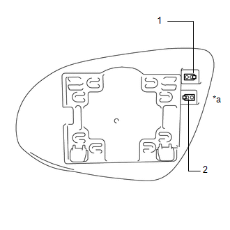
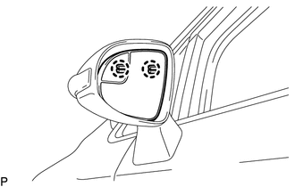
1. INSPECT OUTER MIRROR RH
|
(a) Check the outer mirror heater operation. (1) Measure the resistance according to the value(s) in the table below. Standard Resistance:
If the result is not as specified, replace the outer mirror RH. |
|
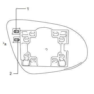
2. INSPECT OUTER MIRROR LH
|
(a) Check the outer mirror heater operation. (1) Measure the resistance according the value(s) in the table below. Standard Resistance:
If the result is not as specified, replace the outer mirror LH. |
|
Removal
REMOVAL
PROCEDURE
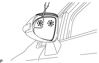
1. REMOVE OUTER MIRROR
|
(a) Push the lower part of the outer mirror surface and tilt it. Text in Illustration
|
|
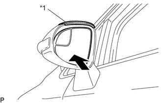
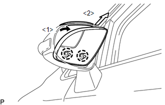
(b) Apply protective tape as shown in the illustration.
|
(c) Using a clip remover, disengage the 2 claws at the upper part of the outer mirror. |
|
|
(d) Disengage the 2 claws and disconnect the outer mirror as shown in the illustration. |
|
|
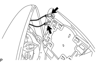
(e) Disconnect the 2 connectors and remove the outer mirror. |
|
Installation
INSTALLATION
PROCEDURE
1. INSTALL OUTER MIRROR
(a) Connect the 2 connectors.
|
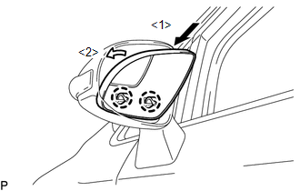
(b) Engage the 2 claws on the lower part of the outer mirror to the outer rear view mirror assembly as shown in the illustration. |
|
|
(c) Engage the 2 claws on the upper part of the outer mirror to the outer rear view mirror assembly. |
|
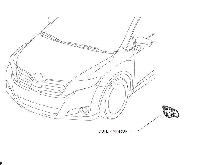
 Outer Rear View Mirror Cover
Components
COMPONENTS
ILLUSTRATION
Installation
INSTALLATION
PROCEDURE
1. INSTALL OUTER MIRROR COVER
(a) Engage the 7 claws to install the outer mirror cover.
...

Other materials about Toyota Venza:
Rear Power Window RH Auto Up / Down Function does not Operate with Rear Power
Window Switch RH
DESCRIPTION
If the manual up/down function can be performed but the auto up/down function
cannot, the fail-safe mode may be functioning.
If the power window initialization (See page
) has not been performed, the auto up/down function
will not operate.
...
Position Initialization Incomplete (B2343)
DESCRIPTION
This DTC is output when the sliding roof ECU (sliding roof drive gear sub-assembly)
has not been initialized.
DTC Code
DTC Detection Condition
Trouble Area
B2343
Sliding roof ECU (sli ...
How To Proceed With Troubleshooting
CAUTION / NOTICE / HINT
HINT:
The TCM of this system is connected to the CAN communication system.
Therefore, before starting troubleshooting, make sure to check that there
is no trouble in the CAN and multiplex communication system.
*: U ...

0.1715