Toyota Venza: Open or Short Circuit in ABS Solenoid Relay Circuit (C0278/11)
DESCRIPTION
The ABS solenoid relay supplies power to the ABS solenoid and TRAC solenoid.
The solenoid relay is turned on 1.5 seconds after the ignition switch is turned to ON, and is turned off if an open or short in the solenoid is detected by self diagnosis performed when the vehicle starts running.
The ABS solenoid relay is housed in the skid control ECU in the brake actuator assembly.
|
DTC Code |
DTC Detection Condition |
Trouble Area |
|---|---|---|
|
C0278/11 |
Either of the following is detected:
|
|
WIRING DIAGRAM
Refer to DTCs C0226/21, C0236/22, C0246/23, C0256/24, C1225/25, C1226/26, C1227/27
and C1228/28 (See page .gif) ).
).
CAUTION / NOTICE / HINT
HINT:
When C1241/41 is output together with C0278/11, inspect and repair the trouble
areas indicated by C1241/41 first (See page ).
PROCEDURE
|
1. |
INSPECT ABS NO. 2 FUSE |
|
(a) Remove the fusible link block from the engine room relay block. |
|
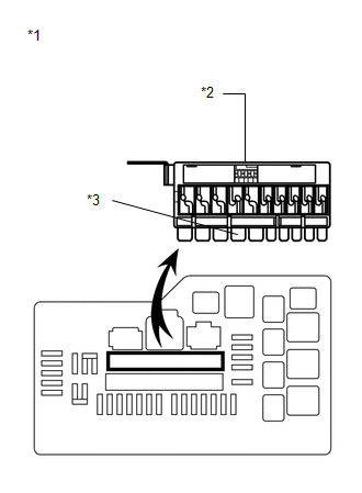
(b) Check if the fusible link is melted.
OK:
The fusible link is not melted.
(c) Measure the resistance according to the value(s) in the table below.
Standard Resistance:
|
Tester Connection |
Condition |
Specified Condition |
|---|---|---|
|
ABS NO. 2 (30 A) fuse - Body ground |
Always |
Below 1 Ω |
|
*1 |
Engine Room Relay Block |
|
*2 |
Fusible Link Block |
|
*3 |
ABS NO. 2 Fuse |
| NG | .gif) |
REPLACE FUSIBLE LINK BLOCK (ABS NO. 2 FUSE) |
|
.gif)
|
2. |
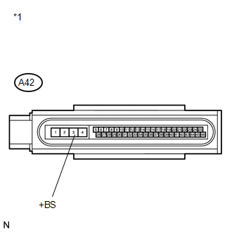
INSPECT SKID CONTROL ECU (+BS TERMINAL) |
|
(a) Install the fusible link block to the engine room relay block. |
|
(b) Make sure that there is no looseness at the locking part and the connecting part of the connector.
(c) Disconnect the skid control ECU connector.
(d) Measure the voltage according to the value(s) in the table below.
Standard Voltage:
|
Tester Connection |
Condition |
Specified Condition |
|---|---|---|
|
A42-3 (+BS) - Body ground |
Always |
11 to 14 V |
|
*1 |
Front view of wire harness connector (to Brake Actuator (Skid Control ECU)) |
| NG | |
REPAIR OR REPLACE HARNESS OR CONNECTOR (+BS CIRCUIT) |
|
|
3. |
INSPECT SKID CONTROL ECU (GND1 TERMINAL) |
|
(a) Measure the resistance according to the value(s) in the table below. Standard Resistance:
|
|
.png)
| NG | |
REPAIR OR REPLACE HARNESS OR CONNECTOR (GND1 CIRCUIT) |
|
|
4. |
RECONFIRM DTC |
HINT:
This code is detected when a problem is identified in the brake actuator assembly.
The solenoid circuit is located in the brake actuator assembly.
Therefore, solenoid circuit inspection and solenoid unit inspection cannot be performed. Be sure to check if the DTC is output before replacing the brake actuator assembly.
(a) Reconnect the skid control ECU connector.
(b) Clear the DTCs (See page ).
(c) Start the engine.
(d) Drive the vehicle at a speed of 20 km/h (12 mph) or more for 30 seconds or more.
(e) Check if the same DTC is recorded (See page
).
|
Result |
Proceed to |
|---|---|
|
DTC (C0278/11) is not output |
A |
|
DTC (C0278/11) is output |
B |
HINT:
- If a speed signal of 15 km/h (9 mph) or more is input to the skid control ECU, with the ignition switch ON and the stop light switch off, the ECU performs self diagnosis of the motor and solenoid circuits.
- If the normal system code is output (the trouble code is not output), slightly jiggle the connectors, wire harnesses, and fuses of the brake actuator assembly. Make sure that no DTCs are output.
- If any DTCs are output while jiggling a connector or wire harness of the brake actuator assembly (skid control ECU), inspect and repair the connector or wire harness.
- It is suspected that the DTCs were output due to a bad connection of the connector terminal.
| A | |
CHECK FOR INTERMITTENT PROBLEMS |
| B | |
REPLACE BRAKE ACTUATOR ASSEMBLY |
 Engine Control System Malfunction (C1201/51)
DESCRIPTION
If a malfunction in the engine control system is detected, the operations of
VSC and TRAC are prohibited by the fail-safe function. When the signals from the
engine are input normally ...
 Open or Short Circuit in ABS Motor Relay Circuit (C0273/13)
DESCRIPTION
The ABS motor relay supplies power to the ABS pump motor. While the ABS is activated,
the ECU turns the motor relay on and operates the ABS pump motor.
If the voltage supplied to the m ...
Other materials about Toyota Venza:
Installation
INSTALLATION
PROCEDURE
1. INSTALL NO. 1 MANIFOLD CONVERTER INSULATOR
(a) Install the No. 1 manifold converter insulator to the exhaust manifold
converter sub-assembly with the 4 bolts.
Torque:
12 N·m {122 kgf·cm, 9 ft·lbf}
...
Tire information
Typical tire symbols
►Standard tire
►Compact spare tire
1. Tire size
2. DOT and Tire Identification Number (TIN)
3. Location of treadwear indicators
4. Tire ply composition and materials Plies are layers of rubber-coated parallel
cords ...
Components
COMPONENTS
ILLUSTRATION
ILLUSTRATION
ILLUSTRATION
ILLUSTRATION
ILLUSTRATION
...

0.1355