Toyota Venza: Inspection
INSPECTION
PROCEDURE
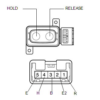
1. INSPECT DRIVER SIDE LUMBAR SWITCH
|
(a) Measure the resistance between the terminals when the switch is operated. Standard Resistance:
If the result is not as specified, replace the switch. |
|
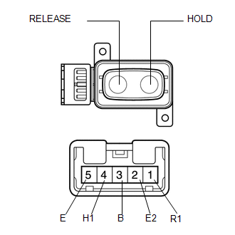
2. INSPECT FRONT PASSENGER SIDE LUMBAR SWITCH
|
(a) Measure the resistance between the terminals when the switch is operated. Standard Resistance:
If the result is not as specified, replace the switch. |
|
 Removal
REMOVAL
PROCEDURE
1. REMOVE FRONT SEAT HEADREST ASSEMBLY
2. REMOVE FRONT SEAT REAR OUTER TRACK COVER
3. REMOVE FRONT SEAT REAR INNER TRACK COVER
4. REMOVE FRONT SEAT ASSEMBLY
5. REMOVE ...
 Installation
INSTALLATION
PROCEDURE
1. INSTALL FRONT POWER SEAT LUMBAR SWITCH
(a) Install the front power seat lumbar switch with the 2 screws.
2. INST ...
Other materials about Toyota Venza:
Fuel Sender Gauge Assembly
Components
COMPONENTS
ILLUSTRATION
Removal
REMOVAL
PROCEDURE
1. DISCHARGE FUEL SYSTEM PRESSURE
(a) Discharge fuel system pressure (See page
).
2. DISCONNECT CABLE FROM NEGATIVE BATTERY TERMINAL
NOTICE:
When disconnecting the cable, some syste ...
Short in Front Passenger Side Squib 2nd Step Circuit (B1815/54-B1818/54)
DESCRIPTION
The front passenger side squib 2nd step circuit consists of the center airbag
sensor assembly and front passenger airbag assembly.
The center airbag sensor assembly uses this circuit to deploy the airbag when
deployment conditions are met.
T ...
Disassembly
DISASSEMBLY
PROCEDURE
1. DISCONNECT CABLE FROM NEGATIVE BATTERY TERMINAL
NOTICE:
When disconnecting the cable, some systems need to be initialized after the cable
is reconnected (See page ).
2. REMOVE REAR DOOR INSIDE HANDLE BEZEL PLUG
(a) ...

0.1335