Toyota Venza: Repair
REPAIR
PROCEDURE
1. REPAIR INTAKE VALVE SEAT
NOTICE:
- Repair the seat while checking the seating position.
- Keep the lip free of foreign matter.
- Take off the cutter gradually to make the intake valve seat smooth.
|
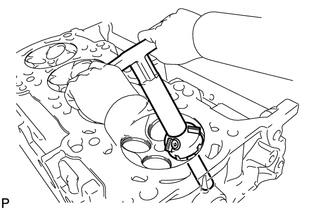
(a) Using a 45° cutter, resurface the valve seat so that the valve seat width is more than the specification. |
|
|
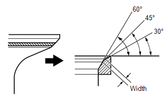
(b) Using 30° and 60° cutters, correct the valve seat so that the valve contacts the entire circumference of the seat. The contact should be in the center of the valve seat, and the valve seat width should be maintained within the specified range around the entire circumference of the seat. Standard width: 1.0 to 1.4 mm (0.0394 to 0.0551 in.) |
|
(c) Hand-lap the valve and valve seat with an abrasive compound.
(d) Check the valve seating position.
2. REPAIR EXHAUST VALVE SEAT
NOTICE:
- Repair the seat while checking the seating position.
- Keep the lip free of foreign matter.
- Take off the cutter gradually to make the exhaust valve seat smooth.
|
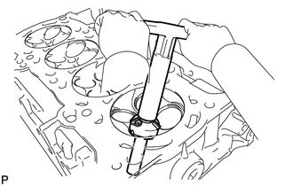
(a) Using a 45° cutter, resurface the valve seat so that the valve seat width is more than the specification. |
|
|
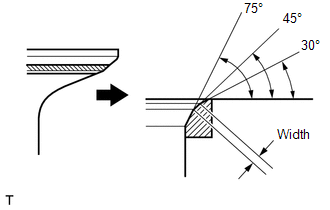
(b) Using 30° and 75° cutters, correct the valve seat so that the valve contacts the entire circumference of the seat. The contact should be in the center of the valve seat, and the valve seat width should be maintained within the specified range around the entire circumference of the seat. Standard width: 1.2 to 1.6 mm (0.0472 to 0.0630 in.) |
|
(c) Hand-lap the valve and valve seat with an abrasive compound.
(d) Check the valve seating position.
 Reassembly
REASSEMBLY
CAUTION / NOTICE / HINT
HINT:
Perform "Inspection After Repair" after replacing the cylinder head sub-assembly
(See page ).
PROCEDURE
1. INSTALL SPARK PLUG TUBE
HINT:
Wh ...

Other materials about Toyota Venza:
Inspection
INSPECTION
PROCEDURE
1. INSPECT VACUUM SWITCHING VALVE ASSEMBLY (for ACIS)
(a) Measure the resistance according to the value(s) in the table below.
Text in Illustration
*1
Body Ground
Stan ...
Removal
REMOVAL
CAUTION / NOTICE / HINT
HINT:
Perform "Inspection After Repair" after replacing the fuel injector assembly
(See page ).
PROCEDURE
1. DISCHARGE FUEL SYSTEM PRESSURE
(a) Discharge fuel system pressure (See page
).
2. DISCONNECT CABL ...
Precaution
PRECAUTION
NOTICE:
When disconnecting the cable from the negative (-) battery terminal, initialize
the following systems after the cable is reconnected.
System Name
See Procedure
Back Door Closer System
...

0.1267