Toyota Venza: Open in Front Passenger Side Electrical Antenna Circuit (B27A2)
DESCRIPTION
The certification ECU (smart key ECU assembly) generates a request signal and sends it to the door electrical key oscillator built into the front door outside handle assembly (for front passenger side) at 0.25-second intervals. To detect a key near the front passenger door, the front door outside handle assembly (for front passenger side) creates a detection area with a radius of approximately 1.0 m (3.28 ft.) from the front passenger door at 0.25-second intervals.
DTC B27A2 is detected by the certification ECU (smart key ECU assembly) if an open circuit is detected between the certification ECU (smart key ECU assembly) and front door outside handle assembly (for front passenger side) terminals (between CLG2 and ANT1, or CG2B and ANT2).
|
DTC No. |
DTC Detection Condition |
Trouble Area |
|---|---|---|
|
B27A2 |
Open circuit detected between the certification ECU (smart key ECU assembly) and front door outside handle assembly (for front passenger side) terminals (between CLG2 and ANT1, or CG2B and ANT2). |
|
WIRING DIAGRAM

CAUTION / NOTICE / HINT
NOTICE:
The smart key system (for entry function) uses a multiplex communication system
(LIN communication system) and CAN communication system. Inspect the communication
function by following How to Proceed with Troubleshooting (See page
.gif) ). Troubleshoot the smart key system (for entry
). Troubleshoot the smart key system (for entry
function) after confirming that the communication system is functioning properly.
PROCEDURE
|
1. |
CHECK CONNECTOR CONNECTION CONDITION |
(a) Turn the engine switch off.
(b) Check that the connectors are properly connected to the certification ECU (smart key ECU assembly) and the front door outside handle assembly (for front passenger side).
OK:
Connectors are properly connected.
| NG | .gif) |
CONNECT CONNECTORS PROPERLY |
|
.gif)
|
2. |
CHECK HARNESS AND CONNECTOR (CERTIFICATION ECU - FRONT DOOR OUTSIDE HANDLE) |
(a) Disconnect the certification ECU (smart key ECU assembly) connector.
|
(b) Disconnect the front door outside handle assembly (for front passenger side) connector. |
|
(c) Measure the resistance according to the value(s) in the table below.
Standard Resistance:
|
Tester Connection |
Condition |
Specified Condition |
|---|---|---|
|
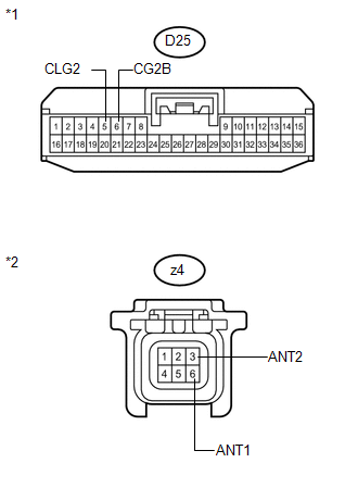
D25-5 (CLG2) - z4-6 (ANT1) |
Always |
Below 1 Ω |
|
D25-6 (CG2B) - z4-3 (ANT2) |
Always |
Below 1 Ω |
|
D25-5 (CLG2) - Body ground |
Always |
10 kΩ or higher |
|
D25-6 (CG2B) - Body ground |
Always |
10 kΩ or higher |
|
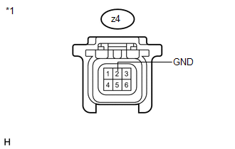
z4-6 (ANT1) - Body ground |
Always |
10 kΩ or higher |
|
z4-3 (ANT2) - Body ground |
Always |
10 kΩ or higher |
|
*1 |
Front view of wire harness connector (to Certification ECU (Smart Key ECU Assembly)) |
|
*2 |
Front view of wire harness connector (to Front Door Outside Handle Assembly (for Front Passenger Side)) |
| NG | |
REPAIR OR REPLACE HARNESS OR CONNECTOR |
|
|
3. |
CHECK HARNESS AND CONNECTOR (FRONT DOOR OUTSIDE HANDLE - BODY GROUND) |
|
(a) Measure the resistance according to the value(s) in the table below. Standard Resistance:
|
|
| NG | |
REPAIR OR REPLACE HARNESS OR CONNECTOR |
|
|
4. |
INSPECT CERTIFICATION ECU (SMART KEY ECU ASSEMBLY) (DOOR ELECTRICAL KEY OSCILLATOR SIGNAL OUTPUT) |
|
(a) Reconnect the certification ECU (smart key ECU assembly) connector. |
|
(b) Measure the resistance and check for pulses according to the value(s) in the table below.
Standard Resistance:
|
Tester Connection |
Condition |
Specified Condition |
|---|---|---|
|
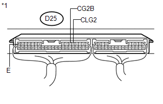
D25-15 (E) - Body ground |
Always |
Below 1 Ω |
Standard:
|
Tester Connection |
Condition |
Specified Condition |
|---|---|---|
|
D25-5 (CLG2) - D25-15 (E) |
|
No pulse generation |
|
D25-5 (CLG2) - D25-15 (E) |
|
Pulse generation |
|
D25-6 (CG2B) - D25-15 (E) |
|
No pulse generation |
|
D25-6 (CG2B) - D25-15 (E) |
|
Pulse generation |
|
*1 |
Component with harness connected (Certification ECU (Smart Key ECU Assembly)) |
| NG | |
REPLACE CERTIFICATION ECU (SMART KEY ECU ASSEMBLY) |
|
|
5. |
REPLACE FRONT DOOR OUTSIDE HANDLE ASSEMBLY (for Front Passenger Side) |
(a) Replace the front door outside handle assembly (for front passenger side)
(See page ).
|
|
6. |
CHECK DTC OUTPUT |
(a) Clear the DTCs (See page ).
(b) Recheck for DTCs.
OK:
DTC B27A2 is not output.
| OK | |
END (FRONT DOOR OUTSIDE HANDLE ASSEMBLY WAS DEFECTIVE) |
| NG | |
REPLACE CERTIFICATION ECU (SMART KEY ECU ASSEMBLY) |
 Open in Driver Side Electrical Antenna Circuit (B27A1)
DESCRIPTION
The certification ECU (smart key ECU assembly) generates a request signal and
sends it to the electrical key oscillator built into the front door outside handle
assembly (for driver s ...
 Entry Answer-back Buzzer does not Sound
DESCRIPTION
The smart key system uses the wireless door lock buzzer to perform various vehicle
exterior warnings. When the conditions for each warning are met, the certification
ECU (smart key EC ...
Other materials about Toyota Venza:
Runnable Signal Malfunction (B2286,P0335)
DESCRIPTION
The power management control ECU receives an engine speed signal and information
that indicates whether the engine is running or not. It receives the engine speed
signal from the ECM via a direct line, and the information about whether the eng ...
Removal
REMOVAL
PROCEDURE
1. REMOVE FRONT SEAT HEADREST ASSEMBLY
2. REMOVE FRONT SEAT REAR OUTER TRACK COVER
3. REMOVE FRONT SEAT REAR INNER TRACK COVER
4. REMOVE FRONT SEAT ASSEMBLY
5. REMOVE RECLINING POWER SEAT SWITCH KNOB
6. REMOVE SLIDE AND VER ...
Installation
INSTALLATION
PROCEDURE
1. INSTALL SEPARATE TYPE FRONT SEATBACK COVER
(a) Using a tacker, install the separate type front seatback heater to
the end of the separate type front seatback cover with 12 new tack pins.
NOTICE:
Be careful not ...

0.1594