Toyota Venza: Open in Driver Side Electrical Antenna Circuit (B27A1)
DESCRIPTION
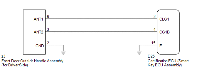
The certification ECU (smart key ECU assembly) generates a request signal and sends it to the electrical key oscillator built into the front door outside handle assembly (for driver side) at 0.25-second intervals. To detect a key near the driver door, the front door outside handle assembly (for driver side) creates a detection area with a radius of approximately 1.0 m (3.28 ft.) from the driver door at 0.25-second intervals.
DTC B27A1 is detected by the certification ECU (smart key ECU assembly) if an open circuit is detected between the certification ECU (smart key ECU assembly) and front door outside handle assembly (for driver side) terminals (between CLG1 and ANT1, or CG1B and ANT2).
|
DTC No. |
DTC Detection Condition |
Trouble Area |
|---|---|---|
|
B27A1 |
Open circuit detected between the certification ECU (smart key ECU assembly) and front door outside handle assembly (for driver side) terminals (between CLG1 and ANT1, or CG1B and ANT2). |
|
WIRING DIAGRAM
CAUTION / NOTICE / HINT
NOTICE:
The smart key system (for entry function) uses a multiplex communication system
(LIN communication system) and CAN communication system. Inspect the communication
function by following How to Proceed with Troubleshooting (See page
.gif) ). Troubleshoot the smart key system (for entry
). Troubleshoot the smart key system (for entry
function) after confirming that the communication system is functioning properly.
PROCEDURE
|
1. |
CHECK CONNECTOR (CONNECTOR CONNECTION CONDITION) |
(a) Turn the engine switch off.
(b) Check that the connectors are properly connected to the certification ECU (smart key ECU assembly) and the front door outside handle assembly (for driver side).
OK:
Connectors are properly connected.
| NG | .gif) |
CONNECT CONNECTORS PROPERLY |
|
.gif)
|
2. |
CHECK HARNESS AND CONNECTOR (CERTIFICATION ECU - FRONT DOOR OUTSIDE HANDLE) |
(a) Disconnect the certification ECU (smart key ECU assembly) connector.
|
(b) Disconnect the front door outside handle assembly (for driver side) connector. |
|
(c) Measure the resistance according to the value(s) in the table below.
Standard Resistance:
|
Tester Connection |
Condition |
Specified Condition |
|---|---|---|
|
D25-3 (CLG1) - z3-6 (ANT1) |
Always |
Below 1 Ω |
|
D25-4 (CG1B) - z3-3 (ANT2) |
Always |
Below 1 Ω |
|
D25-3 (CLG1) - Body ground |
Always |
10 kΩ or higher |
|
D25-4 (CG1B) - Body ground |
Always |
10 kΩ or higher |
|
z3-6 (ANT1) - Body ground |
Always |
10 kΩ or higher |
|
z3-3 (ANT2) - Body ground |
Always |
10 kΩ or higher |
|
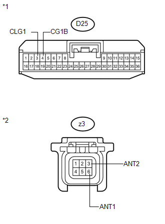
*1 |
Front view of wire harness connector (to Certification ECU (Smart Key ECU Assembly)) |
|
*2 |
Front view of wire harness connector (to Front Door Outside Handle Assembly (for Driver Side)) |
| NG | |
REPAIR OR REPLACE HARNESS OR CONNECTOR |
|
|
3. |
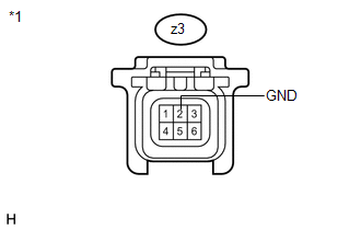
CHECK HARNESS AND CONNECTOR (FRONT DOOR OUTSIDE HANDLE - BODY GROUND) |
|
(a) Measure the resistance according to the value(s) in the table below. Standard Resistance:
|
|
| NG | |
REPAIR OR REPLACE HARNESS OR CONNECTOR |
|
|
4. |
INSPECT CERTIFICATION ECU (SMART KEY ECU ASSEMBLY) (INDOOR ELECTRICAL KEY OSCILLATOR SIGNAL OUTPUT) |
|
(a) Reconnect the certification ECU (smart key ECU assembly) connector. |
|
(b) Measure the resistance and check for pulses according to the value(s) in the table below.
Standard Resistance:
|
Tester Connection |
Condition |
Specified Condition |
|---|---|---|
|
D25-15 (E) - Body ground |
Always |
Below 1 Ω |
Standard:
|
Tester Connection |
Condition |
Specified Condition |
|---|---|---|
|
D25-3 (CLG1) - D25-15 (E) |
|
No pulse generation |
|
D25-3 (CLG1) - D25-15 (E) |
|
Pulse generation |
|
D25-4 (CG1B) - D25-15 (E) |
|
No pulse generation |
|
D25-4 (CG1B) - D25-15 (E) |
|
Pulse generation |
|
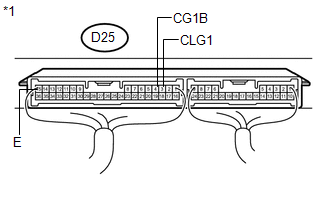
*1 |
Component with harness connected (Certification ECU (Smart Key ECU Assembly)) |
| NG | |
REPLACE CERTIFICATION ECU (SMART KEY ECU ASSEMBLY) |
|
|
5. |
REPLACE FRONT DOOR OUTSIDE HANDLE ASSEMBLY (for Driver Side) |
(a) Replace the front door outside handle assembly (for driver side) (See page
).
|
|
6. |
CHECK DTC OUTPUT |
(a) Clear the DTCs (See page ).
(b) Recheck for DTCs.
OK:
DTC B27A1 is not output.
| OK | |
END (FRONT DOOR OUTSIDE HANDLE ASSEMBLY WAS DEFECTIVE) |
| NG | |
REPLACE CERTIFICATION ECU (SMART KEY ECU ASSEMBLY) |
 Open in Front Floor Electrical Key Oscillator Circuit (B27A5)
DESCRIPTION
The certification ECU (smart key ECU assembly) generates a request signal and
sends it to the indoor electrical key oscillator (for front floor). To detect the
key inside the cabin, t ...
 Open in Front Passenger Side Electrical Antenna Circuit (B27A2)
DESCRIPTION
The certification ECU (smart key ECU assembly) generates a request signal and
sends it to the door electrical key oscillator built into the front door outside
handle assembly (for fro ...
Other materials about Toyota Venza:
Lost Communication with TCM (U0101)
DESCRIPTION
The Transmission Control Module (TCM) and ECM perform 2-way communication with
each other via the Controller Area Network (CAN). The TCM sends signals to the ECM
concerning required engine speed, required engine torque, warning indicators in
...
Key-off Operation Function Operates even if Operating Conditions are not Satisfied
DESCRIPTION
When the front doors are closed, each power window regulator motor assembly
can control its power window operation for approximately 45 seconds after
the ignition switch is turned from ON to off by receiving operation permission
...
Precaution
PRECAUTION
NOTICE:
When disconnecting the cable from the negative (-) battery terminal, initialize
the following systems after the cable is reconnected.
System Name
See Procedure
Back Door Closer System
...

0.1232