Toyota Venza: Disassembly
DISASSEMBLY
PROCEDURE
1. REMOVE FUEL SENDER GAUGE
.gif)
2. SEPARATE FUEL SUCTION PLATE SUB-ASSEMBLY
|
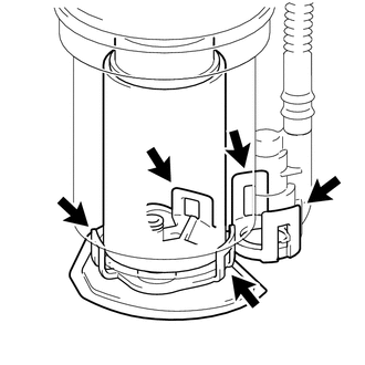
(a) Disconnect the fuel pump connector from the fuel suction plate. NOTICE: Do not damage the wire harness. |
|
.png)
|
(b) Using needle nose pliers, remove the E-ring. Text in Illustration
NOTICE: Do not disconnect the tube shown in the illustration when disassembling the fuel suction tube assembly with pump and gauge. Doing so will cause reassembly of the fuel suction tube assembly with pump and gauge to be impossible as the tube is welded to the plate. |
|
.png)
(c) Separate the fuel suction plate and remove the spring from the sub-tank.
3. REMOVE FUEL FILTER ASSEMBLY
|
(a) Disengage the 2 claws and remove the filter from the sub-tank. |
|
.png)
|
(b) Using a screwdriver with the tip taped, detach the claw of the jet pump nozzle. |
|
.png)
|
(c) Using a screwdriver with the tip taped, remove the jet pump from the sub-tank. |
|
.png)
|
(d) Remove the O-ring from the jet pump. Text in Illustration
|
|
.png)
4. REMOVE FUEL PUMP ASSEMBLY WITH FILTER
|
(a) Disengage the 5 claws on the filter and remove the fuel pump from the fuel filter. NOTICE:
HINT: If the fuel filter assembly is to be replaced, replace the fuel suction plate sub-assembly. |
|
|
(b) Disconnect the fuel pump connector from the fuel pump and then remove the fuel pump harness. |
|
.png)
|
(c) Remove the O-ring and spacer from the fuel pump. NOTICE: Be careful not to damage the sealing surface. HINT: If the O-ring still remains in the fuel filter, remove it using a wire tip (φ1 mm) that is formed as shown in the illustration. |
|
.png)
 Removal
REMOVAL
CAUTION / NOTICE / HINT
HINT:
Perform "Inspection After Repair" after replacing the fuel pump assembly (See
page ).
PROCEDURE
1. DISCHARGE FUEL SYSTEM PRESSURE
(a) Discharge ...
 Inspection
INSPECTION
PROCEDURE
1. INSPECT FUEL PUMP ASSEMBLY WITH FILTER
(a) Inspect fuel pump resistance.
(1) Measure the resistance according to the value(s) in the table below.
Standard Resistance:
...
Other materials about Toyota Venza:
Voice is not Recognized
PROCEDURE
1.
CHECK CONDITION
(a) Check if the system voice recognition level is low when recognizing a particular
voice.
Result
Proceed to
System voice recognition level is low with an ...
Precaution
PRECAUTION
NOTICE:
When disconnecting the cable from the negative (-) battery terminal, initialize
the following systems after the cable is reconnected.
System Name
See Procedure
Back Door Closer System
...
Inspection
INSPECTION
PROCEDURE
1. INSPECT NO. 1 ULTRASONIC SENSOR
(a) Measure the resistance according to the value(s) in the table below.
Standard Resistance:
Tester Connection
Condition
Specified ...

0.1704