Toyota Venza: Occupant Classification Sensor Power Supply Circuit Malfunction (B1793)
DESCRIPTION
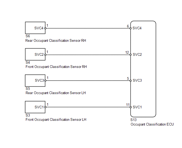
The occupant classification sensor power supply circuit consists of the occupant classification ECU and occupant classification sensors.
DTC B1793 is recorded when a malfunction is detected in the occupant classification sensor power supply circuit.
|
DTC No. |
DTC Detection Condition |
Trouble Area |
|---|---|---|
|
B1793 |
|
|
HINT:
When DTC B1650/32 is detected as a result of troubleshooting for the airbag system, check the DTCs stored in the occupant classification ECU. When DTC B1793 is output, perform troubleshooting for the DTC.
WIRING DIAGRAM
CAUTION / NOTICE / HINT
HINT:
- If troubleshooting (wire harness inspection) is difficult to perform, remove the front passenger seat installation bolts to see under the seat cushion.
- In the above case, hold the seat so that it does not fall down. Hold the seat only as necessary because holding the seat for a long period of time may cause seat rail deformation.
PROCEDURE
|
1. |
CHECK CONNECTORS |
(a) Turn the ignition switch off.
(b) Disconnect the cable from the negative (-) battery terminal.
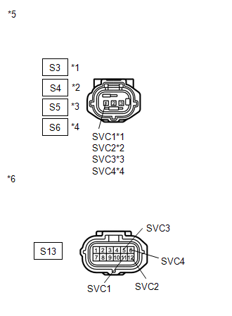
(c) Check that the connectors are properly connected to the 4 occupant classification sensors and occupant classification ECU.
OK:
The connectors are properly connected.
HINT:
If the connectors are not connected securely, reconnect the connectors and proceed to the next inspection.
(d) Disconnect the connectors from the 4 occupant classification sensors and occupant classification ECU.
(e) Check that the terminals of connectors are not damaged.
OK:
The terminals are not deformed or damaged.
| NG | .gif) |
REPLACE FRONT SEAT WIRE RH |
|
.gif)
|
2. |
CHECK FRONT SEAT WIRE RH (SHORT TO B+) |
|
(a) Connect the cable to the negative (-) battery terminal. |
|
(b) Turn the ignition switch to ON.
(c) Measure the voltage according to the value(s) in the table below.
Standard Voltage:
|
Tester Connection |
Switch Condition |
Specified Condition |
|---|---|---|
|
S13-5 (SVC3) - Body ground |
Ignition switch ON |
Below 1 V |
|
S13-6 (SVC4) - Body ground |
Ignition switch ON |
Below 1 V |
|
S13-11 (SVC1) - Body ground |
Ignition switch ON |
Below 1 V |
|
S13-12 (SVC2) - Body ground |
Ignition switch ON |
Below 1 V |
|
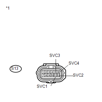
*1 |
Front view of wire harness connector (to Occupant Classification ECU) |
| NG | |
REPLACE FRONT SEAT WIRE RH |
|
|
3. |
CHECK FRONT SEAT WIRE RH (SHORT TO GROUND) |
|
(a) Turn the ignition switch off. |
|
(b) Disconnect the cable from the negative (-) battery terminal.
(c) Measure the resistance according to the value(s) in the table below.
Standard Resistance:
|
Tester Connection |
Condition |
Specified Condition |
|---|---|---|
|
S13-5 (SVC3) - Body ground |
Always |
1 MΩ or higher |
|
S13-6 (SVC4) - Body ground |
Always |
1 MΩ or higher |
|
S13-11 (SVC1) - Body ground |
Always |
1 MΩ or higher |
|
S13-12 (SVC2) - Body ground |
Always |
1 MΩ or higher |
|
*1 |
Front view of wire harness connector (to Occupant Classification ECU) |
| NG | |
REPLACE FRONT SEAT WIRE RH |
|
|
4. |
CHECK FRONT SEAT WIRE RH (OPEN) |
|
(a) Measure the resistance according to the value(s) in the table below. Standard Resistance:
|
|
| NG | |
REPLACE FRONT SEAT WIRE RH |
|
|
5. |
CHECK FRONT SEAT WIRE RH (SHORT) |
|
(a) Measure the resistance according to the value(s) in the table below. Standard Resistance:
|
|
| NG | |
REPLACE FRONT SEAT WIRE RH |
|
|
6. |
CHECK DTC |
(a) Connect the connectors to the occupant classification ECU and the 4 occupant classification sensors.
(b) Connect the cable to the negative (-) battery terminal.
(c) Turn the ignition switch to ON.
(d) Clear the DTCs stored in the occupant classification ECU (See page
.gif) ).
).
(e) Clear the DTCs stored in the center airbag sensor assembly (See page
).
(f) Turn the ignition switch off.
(g) Turn the ignition switch to ON.
(h) Check for DTCs (See page ).
OK:
DTC B1793 is not output.
HINT:
Codes other than DTC B1793 may be output at this time, but they are not related to this check.
| OK | |
USE SIMULATION METHOD TO CHECK |
|
|
7. |
REPLACE OCCUPANT CLASSIFICATION ECU |
(a) Turn the ignition switch off.
(b) Disconnect the cable from the negative (-) battery terminal.
(c) Replace the occupant classification ECU (See page
).
HINT:
Perform the inspection using parts from a normal vehicle if possible.
|
|
8. |
PERFORM ZERO POINT CALIBRATION |
(a) Connect the cable to the negative (-) battery terminal.
(b) Connect the Techstream to the DLC3.
(c) Turn the ignition switch to ON.
(d) Using the Techstream, perform Zero Point Calibration (See page
).
OK:
"Zero Point Calibration is complete." is displayed.
| NG | |
GO TO STEP 11 |
|
|
9. |
PERFORM SENSITIVITY CHECK |
(a) Using the Techstream, perform Sensitivity Check (See page
).
Standard:
27 to 33 kg (59.5 to 72.8 lb)
| NG | |
GO TO STEP 11 |
|
|
10. |
CHECK DTC |
(a) Turn the ignition switch to ON.
(b) Clear the DTCs stored in the occupant classification ECU (See page
).
(c) Clear the DTCs stored in the center airbag sensor assembly (See page
).
(d) Turn the ignition switch off.
(e) Turn the ignition switch to ON.
(f) Check for DTCs (See page ).
OK:
DTC B1793 is not output.
HINT:
Codes other than DTC B1793 may be output at this time, but they are not related to this check.
| OK | |
END |
|
|
11. |
REPLACE FRONT SEAT FRAME WITH ADJUSTER ASSEMBLY RH |
(a) Turn the ignition switch off.
(b) Disconnect the cable from the negative (-) battery terminal.
(c) Replace the front seat frame with adjuster assembly RH (See page
for power seat or
for manual seat).
|
|
12. |
PERFORM ZERO POINT CALIBRATION |
(a) Connect the cable to the negative (-) battery terminal.
(b) Connect the Techstream to the DLC3.
(c) Turn the ignition switch to ON.
(d) Using the Techstream, perform Zero Point Calibration (See page
).
OK:
"Zero Point Calibration is complete." is displayed.
|
|
13. |
PERFORM SENSITIVITY CHECK |
(a) Using the Techstream, perform Sensitivity Check (See page
).
Standard:
27 to 33 kg (59.5 to 72.8 lb)
| NEXT | |
END |
 Occupant Classification ECU Malfunction (B1795)
DESCRIPTION
DTC B1795 is recorded when a malfunction is detected in the occupant classification
ECU.
Troubleshoot DTC B1771 first if DTCs B1771 and B1795 are output simultaneously.
DTC ...
 Open in Occupant Classification ECU Battery Positive Line (B1794)
DESCRIPTION
This circuit consists of the occupant classification ECU and power source circuit
(battery, fuse and wire harness).
DTC B1794 is recorded when a malfunction is detected in the occupant ...
Other materials about Toyota Venza:
Fail-safe Chart
FAIL-SAFE CHART
1. FAIL-SAFE OPERATION
If there is a problem with sensor signals or actuator systems, the skid
control ECU prohibits power supply to the brake actuator assembly and informs
the ECM of VSC system malfunction.
The brake actuat ...
Interior Light Circuit
DESCRIPTION
The illuminated entry system controls the roof console box assembly, step or
spot light assembly and transponder key amplifier*1.
HINT:
*1: w/o Smart Key System
WIRING DIAGRAM
PROCEDURE
1.
PERFORM ACTIVE TEST USING ...
Engine Coolant Temperature Receiver Gauge Malfunction
DESCRIPTION
In this circuit, the meter CPU receives engine coolant temperature signals from
the ECM using the CAN communication system (CAN No. 1 Bus). The meter CPU displays
engine coolant temperature that is calculated based on the data received from th ...

0.1587