
Toyota Venza: Diagnosis System
DIAGNOSIS SYSTEM
1. CHECK DLC3
(a) Check the DLC3 (See page .gif) ).
).
2. FUNCTION OF PASSENGER AIRBAG ON/OFF INDICATOR
(a) Initial check.
(1) Turn the ignition switch to ON.
(2) The passenger airbag ON/OFF indicator ("ON" and "OFF") comes on for approximately 4 seconds, then goes off for approximately 2 seconds.
(3) Approximately 6 seconds after the ignition switch is turned to ON, the passenger airbag ON/OFF indicator will show ON or OFF depending on the conditions listed below.
|
Front Passenger Seat Condition |
Passenger Airbag ON/OFF Indicator |
SRS Warning Light |
|
|---|---|---|---|
|
ON Indicator |
OFF Indicator |
||
|
Vacant |
OFF |
OFF |
OFF |
|
Adult is seated. |
ON |
OFF |
OFF |
|
Child is seated. |
OFF |
ON |
OFF |
|
Child restraint system is set. |
OFF |
ON |
OFF |
|
Occupant classification system failure |
OFF |
ON |
ON |
HINT:
- The passenger airbag ON/OFF indicator is based on the timing chart below in order to check the indicator light circuit.
- When the occupant classification system has trouble, both the SRS warning light and passenger airbag ON/OFF indicator ("OFF") come on. In this case, check the DTCs in the airbag system first.
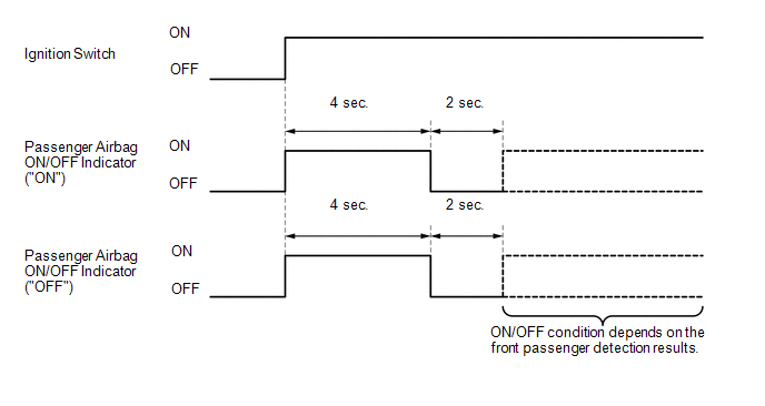
3. CHECK PASSENGER AIRBAG ON/OFF INDICATOR
(a) Turn the ignition switch to ON.
.png)
(b) Check that the passenger airbag ON/OFF indicator (ON and OFF) comes on for approximately 4 seconds, then goes off for approximately 2 seconds.
HINT:
Refer to the table in step 3 regarding the passenger airbag ON/OFF indicator when the ignition switch is turned to ON and approximately 6 seconds pass.
 Terminals Of Ecu
TERMINALS OF ECU
1. OCCUPANT CLASSIFICATION ECU (for Power Seat)
Terminal No. (Symbol)
Wiring Color
Terminal Description
Condition
Specificat ...
 Dtc Check / Clear
DTC CHECK / CLEAR
HINT:
Use the Techstream to read and clear the DTC of the occupant classification ECU,
otherwise the DTCs cannot be read and cleared.
1. DTC CHECK
(a) Turn the ignition switch ...
Other materials about Toyota Venza:
Stop Light Switch
Components
COMPONENTS
ILLUSTRATION
Removal
REMOVAL
PROCEDURE
1. REMOVE STOP LIGHT SWITCH ASSEMBLY
(a) Disconnect the connector.
(b) Turn the stop light switch assembly countercl ...
Installation
INSTALLATION
PROCEDURE
1. INSTALL LUMBAR SUPPORT ADJUSTER ASSEMBLY
(a) Install the bush.
(b) Install the lumbar support adjuster assembly with the guide and 2
screws.
...
Slide Sensor Malfunction (B2650)
DESCRIPTION
When the position control ECU and switch assembly does not receive a sensor signal
despite forward or backward movement of seat by power seat motor operation, this
DTC is output.
DTC Code
DTC Detection Condition
...

0.1637