Toyota Venza: Diagnosis Circuit
DESCRIPTION
This circuit is used to read the DTCs that are output from the transponder key ECU assembly with the Techstream.
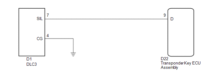
WIRING DIAGRAM
CAUTION / NOTICE / HINT
NOTICE:
If the transponder key ECU assembly is replaced, register the key and ECU communication
ID (See page .gif) ).
).
PROCEDURE
|
1. |
CHECK HARNESS AND CONNECTOR (DLC3 - TRANSPONDER KEY ECU AND BODY GROUND) |
|
(a) Disconnect the transponder key ECU assembly connector. |
|
(b) Measure the resistance according to the value(s) in the table below.
Standard Resistance:
|
Tester Connection |
Condition |
Specified Condition |
|---|---|---|
|
D22-9 (D) - D1-7 (SIL) |
Always |
Below 1 Ω |
|
D1-4 (CG) - Body ground |
Always |
Below 1 Ω |
|
D22-9 (D) - Body ground |
Always |
10 kΩ or higher |
|
D1-7 (SIL)- Body ground |
Always |
10 kΩ or higher |
|
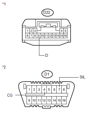
*1 |
Front view of wire harness connector (to Transponder Key ECU Assembly) |
|
*2 |
Front view of wire harness connector (to DLC3) |
| OK | .gif) |
REPLACE TRANSPONDER KEY ECU ASSEMBLY |
| NG | |
REPAIR OR REPLACE HARNESS OR CONNECTOR |
 ECU Power Source Circuit
DESCRIPTION
This circuit provides power to operate the transponder key ECU assembly.
WIRING DIAGRAM
CAUTION / NOTICE / HINT
NOTICE:
If the transponder key ECU assembly is replaced, register the ...

Other materials about Toyota Venza:
Fail-safe Chart
FAIL-SAFE CHART
1. FAIL-SAFE OPERATION
If there is a problem with sensor signals or actuator systems, the skid
control ECU prohibits power supply to the brake actuator assembly and informs
the ECM of VSC system malfunction.
The brake actuat ...
Installation
INSTALLATION
PROCEDURE
1. INSTALL SEPARATE TYPE FRONT SEAT CUSHION COVER
(a) Using a tacker, install the separate type front seat cushion heater
to the end of the separate type front seat cushion cover with 25 new tack
pins.
NOTICE:
...
Installation
INSTALLATION
PROCEDURE
1. INSTALL REAR DOOR BELT MOULDING
(a) Engage the 5 claws to install the rear door belt moulding.
2. INSTALL REAR DOOR GLASS SUB-ASSEMBLY
3. INSTALL REAR DOOR WINDOW DIVIS ...

0.1279