Toyota Venza: Vehicle Speed Signal Circuit between Stereo Component Amplifier and Combination Meter
DESCRIPTION
The stereo component amplifier assembly receives a vehicle speed signal from the combination meter assembly to control the ASL function.
HINT:
- A voltage of 12 V or 5 V is output from each ECU and then input to the combination meter assembly. The signal is changed to a pulse signal at the transistor in the combination meter assembly. Each ECU controls its respective systems based on this pulse signal.
- If a short occurs in any of the ECUs or in the wire harness connected to an ECU, all systems in the following diagram will not operate normally.
WIRING DIAGRAM
1. for 1AR-FE
.png)
2. for 2GR-FE
.png)
PROCEDURE
|
1. |
INSPECT COMBINATION METER ASSEMBLY (OUTPUT WAVEFORM) |
|
(a) Check the output waveform. (1) Remove the combination meter assembly with the connector(s) still connected. (2) Connect an oscilloscope to terminal E1-16 (+S) and body ground. (3) Turn the ignition switch to ON. (4) Turn a wheel slowly. (5) Check the signal waveform according to the condition(s) in the table below.
OK: The waveform is similar to that shown in the illustration. HINT: When the system is functioning normally, one wheel revolution generates 4 pulses. As the vehicle speed increases, the width indicated by (A) in the illustration narrows. Text in Illustration
|
|
.png)
| NG | .gif) |
GO TO METER / GAUGE SYSTEM |
|
.gif)
|
2. |
INSPECT STEREO COMPONENT AMPLIFIER ASSEMBLY (INPUT WAVEFORM) |
|
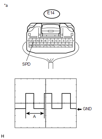
(a) Check the input waveform. (1) Remove the stereo component amplifier assembly with the connector(s) still connected. (2) Connect an oscilloscope to terminal E14-11 (SPD) and body ground. (3) Turn the ignition switch to ON. (4) Turn a wheel slowly. (5) Check the signal waveform according to the condition(s) in the table below.
OK: The waveform is similar to that shown in the illustration. HINT: When the system is functioning normally, one wheel revolution generates 4 pulses. As the vehicle speed increases, the width indicated by (A) in the illustration narrows. Text in Illustration
|
|
| OK | |
PROCEED TO NEXT SUSPECTED AREA SHOWN IN PROBLEM SYMPTOMS TABLE |
|
|
3. |
CHECK HARNESS AND CONNECTOR (STEREO COMPONENT AMPLIFIER ASSEMBLY - JUNCTION CONNECTOR) |
(a) Disconnect the E14 stereo component amplifier assembly connector.
(b) Disconnect the E31 junction connector.
(c) Measure the resistance according to the value(s) in the table below.
Standard Resistance:
|
Tester Connection |
Condition |
Specified Condition |
|---|---|---|
|
E14-11 (SPD) - E31-21 |
Always |
Below 1 Ω |
| NG | |
REPAIR OR REPLACE HARNESS OR CONNECTOR |
|
|
4. |
CHECK HARNESS AND CONNECTOR (COMBINATION METER ASSEMBLY - JUNCTION CONNECTOR) |
(a) Disconnect the E1 combination meter assembly connector.
(b) Disconnect the E31 junction connector.
(c) Measure the resistance according to the value(s) in the table below.
Standard Resistance:
|
Tester Connection |
Condition |
Specified Condition |
|---|---|---|
|
E1-16 (+S) - E31-19 |
Always |
Below 1 Ω |
| OK | |
REPLACE JUNCTION CONNECTOR |
| NG | |
REPAIR OR REPLACE HARNESS OR CONNECTOR |
 Navigation Voice Circuit
DESCRIPTION
This circuit is used when the voice switch of the steering pad switch assembly
is pushed.
Using this circuit, the navigation receiver assembly sends signals to the stereo
component a ...
 Microphone Circuit between Microphone and Navigation Receiver Assembly
DESCRIPTION
The navigation receiver assembly and inner rear view mirror assembly
(amplifier microphone assembly) are connected to each other using the microphone
connection detection s ...
Other materials about Toyota Venza:
Removal
REMOVAL
PROCEDURE
1. REMOVE REAR WHEELS
2. REMOVE CENTER EXHAUST PIPE ASSEMBLY
(a) Remove the center exhaust pipe assembly.
HINT:
Refer to the instructions for Removal of the exhaust pipe (See page
for 2GR-FE,
for 1AR-FE).
3. REMOVE PROPELLER WITH ...
Removal
REMOVAL
PROCEDURE
1. PRECAUTION
CAUTION:
Be sure to read Precaution thoroughly before servicing (See page
).
NOTICE:
After turning the ignition switch off, waiting time may be required before disconnecting
the cable from the negative (-) battery term ...
Engine Coolant Temperature Circuit Range / Performance Problem (P0116)
DESCRIPTION
Refer to DTC P0115 (See page ).
DTC No.
DTC Detection Condition
Trouble Area
P0116
When either of the following conditions is met (2 trip detection logic).
During engine ...

0.1601