Toyota Venza: Disassembly
DISASSEMBLY
PROCEDURE
1. INSPECT FRONT OIL PUMP AND GEAR BODY SUB-ASSEMBLY
.gif)
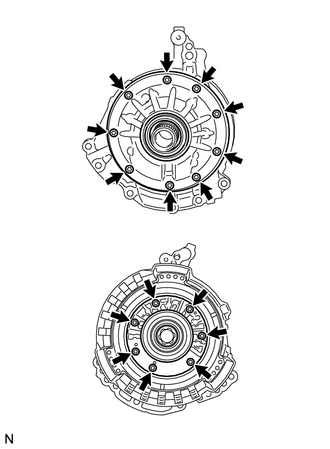
2. REMOVE STATOR SHAFT ASSEMBLY
|
(a) Using a "TORX" wrench (T30), remove the 16 bolts and stator shaft assembly from the oil pump body. NOTICE: Keep the gears in the order of disassembly. |
|
3. INSPECT CLEARANCE OF FRONT OIL PUMP AND GEAR BODY SUB-ASSEMBLY
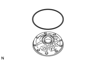
4. REMOVE FRONT OIL PUMP BODY O-RING
|
(a) Remove the O-ring from the oil pump body. |
|
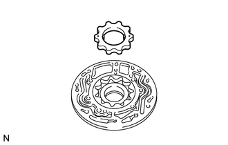
5. REMOVE FRONT OIL PUMP DRIVE GEAR
|
(a) Remove the front oil pump drive gear from the oil pump body. |
|
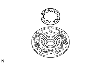
6. REMOVE FRONT OIL PUMP DRIVEN GEAR
|
(a) Remove the front oil pump driven gear from the oil pump body. |
|
7. REMOVE FRONT OIL PUMP OIL SEAL
|
(a) Mount the oil pump in a soft jaw vise. |
|
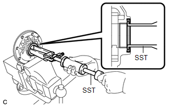
(b) Using SST, remove the oil seal from the oil pump body.
SST: 09308-00010
 Components
COMPONENTS
ILLUSTRATION
...
 Inspection
INSPECTION
PROCEDURE
1. INSPECT FRONT OIL PUMP AND GEAR BODY SUB-ASSEMBLY
(a) Turn the drive gear with 2 screwdrivers and make sure that it rotates
smoothly.
NOTICE:
Be careful ...
Other materials about Toyota Venza:
Portable Player cannot be Connected Manually/Automatically
CAUTION / NOTICE / HINT
HINT:
Some versions of "Bluetooth" compatible audio players may not function properly,
or the functions may be limited using the radio and display receiver assembly, even
if the portable audio player itself can play file ...
License Plate Light Assembly
Components
COMPONENTS
ILLUSTRATION
ILLUSTRATION
Installation
INSTALLATION
PROCEDURE
1. INSTALL LICENSE PLATE LIGHT ASSEMBLY
(a) Engage the 2 claws to install the license plate light assembly.
...
Control Module Performance (P0607)
MONITOR DESCRIPTION
The ECM continuously monitors its internal processors (CPUs) and heated oxygen
sensor transistors. This self-check ensures that the ECM is functioning properly.
DTC No.
DTC Detection Condition
Trouble Ar ...

0.1156