Toyota Venza: Microphone Circuit between Microphone and Radio Receiver
DESCRIPTION
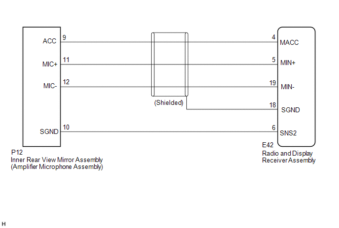
The radio and display receiver assembly and inner rear view mirror assembly (amplifier microphone assembly) are connected to each other using the microphone connection detection signal lines.
Using this circuit, the radio and display receiver assembly sends power to the inner rear view mirror assembly (amplifier microphone assembly), and the inner rear view mirror assembly (amplifier microphone assembly) sends microphone signals to the radio and display receiver assembly.
WIRING DIAGRAM
PROCEDURE
|
1. |
CHECK MICROPHONE (OPERATION CHECK) |
|
(a) Enter the "Microphone Check" screen. Refer to Check Microphone in
Operation Check (See page |
|
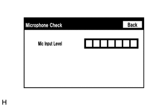
(b) When a voice is input into the microphone, check that the microphone input level meter changes according to the input voice.
OK:
Check result is normal.
| OK | .gif) |
REPLACE RADIO AND DISPLAY RECEIVER ASSEMBLY |
|
.gif)
|
2. |
CHECK HARNESS AND CONNECTOR (RADIO AND DISPLAY RECEIVER ASSEMBLY - INNER REAR VIEW MIRROR ASSEMBLY (AMPLIFIER MICROPHONE ASSEMBLY) |
(a) Disconnect the E42 radio and display receiver assembly connector.
(b) Disconnect the P12 inner rear view mirror assembly (amplifier microphone assembly) connector.
(c) Measure the resistance according to the value(s) in the table below.
Standard Resistance:
|
Tester Connection |
Condition |
Specified Condition |
|---|---|---|
|
E42-4 (MACC) - P12-9 (ACC) |
Always |
Below 1 Ω |
|
E42-5 (MIN+) - P12-11 (MIC+) |
Always |
Below 1 Ω |
|
E42-19 (MIN-) - P12-12 (MIC-) |
Always |
Below 1 Ω |
|
E42-6 (SNS2) - P12-10 (SGND) |
Always |
Below 1 Ω |
|
E42-4 (MACC) - Body ground |
Always |
10 kΩ or higher |
|
E42-5 (MIN+) - Body ground |
Always |
10 kΩ or higher |
|
E42-19 (MIN-) - Body ground |
Always |
10 kΩ or higher |
|
E42-18 (SGND) - Body ground |
Always |
10 kΩ or higher |
|
E42-6 (SNS2) - Body ground |
Always |
10 kΩ or higher |
| NG | |
REPAIR OR REPLACE HARNESS OR CONNECTOR |
|
|
3. |
INSPECT RADIO AND DISPLAY RECEIVER ASSEMBLY |
|
(a) Measure the voltage according to the value(s) in the table below. Standard Voltage:
|
|
(b) Measure the resistance according to the value(s) in the table below.
Standard Resistance:
|
Tester Connection |
Condition |
Specified Condition |
|---|---|---|
|
E42-18 (SGND) - Body ground |
Always |
Below 1 Ω |
|
E42-19 (MIN-) - Body ground |
Always |
Below 1 Ω |
|
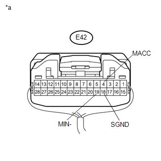
*a |
Component with harness connected (Radio and Display Receiver Assembly) |
| NG | |
REPLACE RADIO AND DISPLAY RECEIVER ASSEMBLY |
|
|
4. |
INSPECT INNER REAR VIEW MIRROR ASSEMBLY (AMPLIFIER MICROPHONE ASSEMBLY) |
(a) Remove the inner rear view mirror assembly (amplifier microphone assembly)
(See page .gif) ).
).
|
(b) Measure the resistance according to the value(s) in the table below. Standard Resistance:
|
|
.png)
| NG | |
REPLACE INNER REAR VIEW MIRROR ASSEMBLY (AMPLIFIER MICROPHONE ASSEMBLY) |
|
|
5. |
INSPECT INNER REAR VIEW MIRROR ASSEMBLY (AMPLIFIER MICROPHONE ASSEMBLY) |
(a) Turn the ignition switch to ACC.
|
(b) Connect an oscilloscope to terminals 11 (MIC+) and 12 (MIC-) of the P12 inner rear view mirror assembly (amplifier microphone assembly) connector. |
|
(c) Check the waveform of the inner rear view mirror assembly (amplifier microphone assembly) using the oscilloscope.
|
Result |
Proceed to |
|---|---|
|
A waveform synchronized with the voice input to the inner rear view mirror assembly (amplifier microphone assembly) is output. |
A |
|
A waveform synchronized with the voice input to the inner rear view mirror assembly (amplifier microphone assembly) is not output. |
B |
|
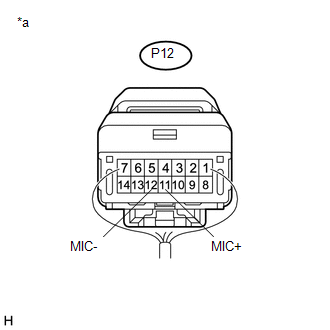
*a |
Component with harness connected (Inner Rear View Mirror Assembly (Amplifier Microphone Assembly)) |
| A | |
PROCEED TO NEXT SUSPECTED AREA SHOWN IN PROBLEM SYMPTOMS TABLE |
| B | |
REPLACE INNER REAR VIEW MIRROR ASSEMBLY (AMPLIFIER MICROPHONE ASSEMBLY) |
 Reverse Signal Circuit
DESCRIPTION
The radio and display receiver assembly receives a reverse signal from the park/neutral
position switch assembly.
WIRING DIAGRAM
PROCEDURE
1.
CHECK BACK-UP L ...
 Radio Receiver Power Source Circuit
DESCRIPTION
This is the power source circuit to operate the radio and display receiver assembly.
WIRING DIAGRAM
CAUTION / NOTICE / HINT
NOTICE:
Inspect the fuses for circuits related to this sy ...
Other materials about Toyota Venza:
Dtc Check / Clear
DTC CHECK / CLEAR
1. CHECK DTC
(a) Connect the Techstream to the DLC3.
(b) Turn the ignition switch to ON.
(c) Turn the Techstream on.
(d) Read the DTCs by following the directions on the Techstream screen.
HINT:
Refer to the Techstream operator's m ...
Purge Valve
Components
COMPONENTS
ILLUSTRATION
Inspection
INSPECTION
PROCEDURE
1. INSPECT NO. 1 VACUUM SWITCHING VALVE ASSEMBLY
(a) Measure the resistance according to the value(s) in the table below.
Standard Resistance:
Te ...
Automatic door locking and unlocking systems
The following functions can be set or canceled:
- Setting and canceling the functions
► Setting and canceling the functions
Vehicles with TFT type multi-information display The function settings can be changed
using the multi-information dis ...

0.1278