Toyota Venza: Reverse Signal Circuit
DESCRIPTION
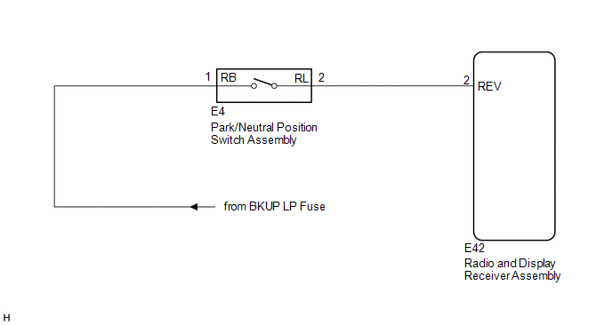
The radio and display receiver assembly receives a reverse signal from the park/neutral position switch assembly.
WIRING DIAGRAM
PROCEDURE
|
1. |
CHECK BACK-UP LIGHT |
(a) Move the shift lever to R and check if the back-up lights come on.
OK:
The back-up lights come on.
| NG | .gif) |
GO TO LIGHTING SYSTEM |
|
.gif)
|
2. |
CHECK HARNESS AND CONNECTOR (REVERSE SIGNAL) |
(a) Disconnect the E42 radio and display receiver assembly connector.
(b) Measure the voltage according to the value(s) in the table below.
Standard Voltage:
|
Tester Connection |
Condition |
Specified Condition |
|---|---|---|
|
E42-2 (REV) - Body ground |
Ignition switch ON Shift lever in R |
11 to 14 V |
|
E42-2 (REV) - Body ground |
Ignition switch ON Shift lever in any position other than R |
Below 1 V |
| OK | |
PROCEED TO NEXT SUSPECTED AREA SHOWN IN PROBLEM SYMPTOMS TABLE |
| NG | |
REPAIR OR REPLACE HARNESS OR CONNECTOR |
 Data Signal Circuit between Radio Receiver and Extension Module
DESCRIPTION
The stereo component tuner assembly sends the image data signal to the radio
and display receiver assembly via this circuit.
WIRING DIAGRAM
PROCEDURE
1.
CHEC ...
 Microphone Circuit between Microphone and Radio Receiver
DESCRIPTION
The radio and display receiver assembly and inner rear view mirror assembly (amplifier
microphone assembly) are connected to each other using the microphone connection
detection signa ...
Other materials about Toyota Venza:
Components
COMPONENTS
ILLUSTRATION
ILLUSTRATION
ILLUSTRATION
ILLUSTRATION
ILLUSTRATION
ILLUSTRATION
...
Removal
REMOVAL
PROCEDURE
1. REMOVE ENGINE ASSEMBLY WITH TRANSAXLE
See page for 2GR-FE
See page for 1AR-FE
2. REMOVE FRONT NO. 1 STABILIZER BRACKET LH
3. REMOVE FRONT NO. 1 STABILIZER BRACKET RH
HINT:
Perform the same procedure as for the LH side.
4. REM ...
Theft Deterrent System Communication Line High Fixation (B279A)
DESCRIPTION
If the communication line (EFIO - IMI) to the certification ECU (smart key ECU
assembly) is stuck high output (e.g. shorted to +B), the ECM stores this DTC.
DTC No.
DTC Detection Condition
Trouble Area
...

0.1321