Toyota Venza: Linear Solenoid Circuit (C1298/98)
DESCRIPTION
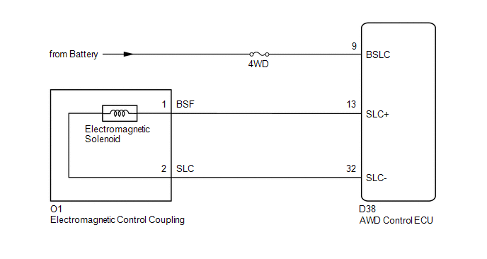
The AWD control ECU receives signals from each sensor to control clutch pressure to distribute torque according to the driving conditions.
|
DTC No. |
DTC Detection Condition |
Trouble Area |
|---|---|---|
|
C1298/98 |
When the following continues for 1 second or more: - With the current of the 0.8 A or more, an open or short in the electromagnetic solenoid circuit occurs. |
|
WIRING DIAGRAM
CAUTION / NOTICE / HINT
NOTICE:
Inspect the fuses for circuits related to this system before performing the following inspection procedure.
HINT:
Check the condition of each related circuit connector before troubleshooting
(See page .gif) ).
).
PROCEDURE
|
1. |
CHECK WIRE HARNESS (AWD CONTROL ECU - BATTERY) |
|
(a) Disconnect the ECU connector. |
|
(b) Measure the voltage of the wire harness side connector.
Standard Voltage:
|
Tester Connection |
Condition |
Specified Condition |
|---|---|---|
|
D38-9 (BSLC) - Body Ground |
Always |
11 to 14 V |
|
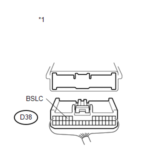
*1 |
Rear view of wire harness connector (to AWD Control ECU) |
| NG | .gif) |
REPAIR OR REPLACE HARNESS OR CONNECTOR |
|
.gif)
|
2. |
INSPECT ELECTRO MAGNETIC CONTROL COUPLING (ELECTROMAGNETIC SOLENOID) |
|
(a) Remove the coupling connector. |
|
(b) Measure the resistance of the solenoid.
Standard Resistance:
|
Tester Connection |
Condition |
Specified Condition |
|---|---|---|
|
1 (BSF) - 2 (SLC) |
Always |
2.2 to 2.6 Ω |
|
1 (BSF) - Body ground |
Always |
10 kΩ or higher |
|
2 (SLC) - Body ground |
Always |
10 kΩ or higher |
|
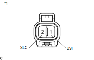
*1 |
Electromagnetic Solenoid |
| NG | |
REPLACE ELECTRO MAGNETIC CONTROL COUPLING |
|
|
3. |
CHECK WIRE HARNESS (ELECTROMAGNETIC CONTROL COUPLING - AWD CONTROL ECU) |
|
(a) Disconnect the ECU connector. |
|
(b) Measure the resistance of the wire harness side connector.
Standard Resistance:
|
Tester Connection |
Condition |
Specified Condition |
|---|---|---|
|
D38-13 (SLC+) - O1-1 (BSF) |
Always |
Below 1 Ω |
|
D38-32 (SLC-) - O1-2 (SLC) |
Always |
Below 1 Ω |
|
D38-13 (SLC+) - Body ground |
Always |
10 kΩ or higher |
|
D38-32 (SLC-) - Body ground |
Always |
10 kΩ or higher |
|
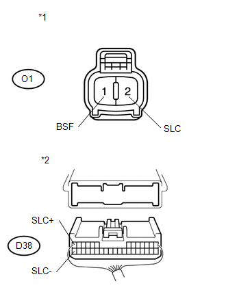
*1 |
Front view of wire harness connector (to Electromagnetic Solenoid) |
|
*2 |
Rear view of wire harness connector (to AWD Control ECU) |
| OK | |
REPLACE AWD CONTROL ECU |
| NG | |
REPAIR OR REPLACE HARNESS OR CONNECTOR |
 ABS Malfunction (C1296/96)
DESCRIPTION
If a malfunction in the speed sensor signal circuit occurs, the AWD control ECU
will output this DTC.
DTC No.
DTC Detecting Condition
Trouble Area
...
 Engine Circuit Malfunction (C1280/82)
DESCRIPTION
If a malfunction in the ECM circuit occurs, the AWD control ECU will output this
DTC.
DTC No.
DTC Detection Condition
Trouble Area
C12 ...
Other materials about Toyota Venza:
IG Power Source Circuit
DESCRIPTION
The main power source is supplied to the A/C amplifier when the ignition switch
is ON.
The power source is used for operating the A/C amplifier and servo motor, etc.
WIRING DIAGRAM
CAUTION / NOTICE / HINT
NOTICE:
Inspect the fuses for cir ...
Components
COMPONENTS
ILLUSTRATION
ILLUSTRATION
ILLUSTRATION
ILLUSTRATION
ILLUSTRATION
...
Installation
INSTALLATION
PROCEDURE
1. INSTALL THROTTLE BODY ASSEMBLY
(a) Install a new gasket to the intake manifold.
(b) Install the fuel tube bracket with the bolt.
Torque:
7.5 N·m {76 kgf ...

0.1128