Toyota Venza: Components
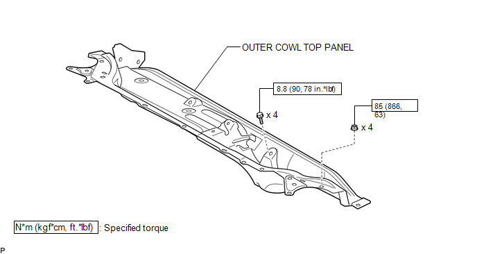
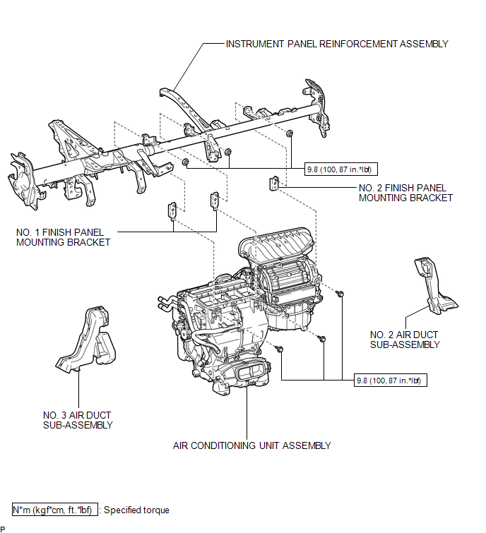
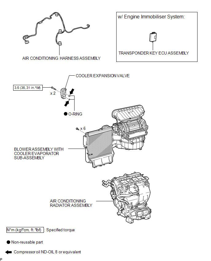
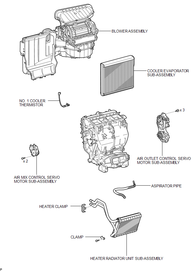
COMPONENTS
ILLUSTRATION
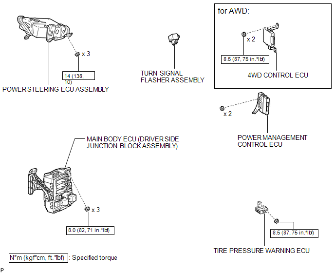
ILLUSTRATION
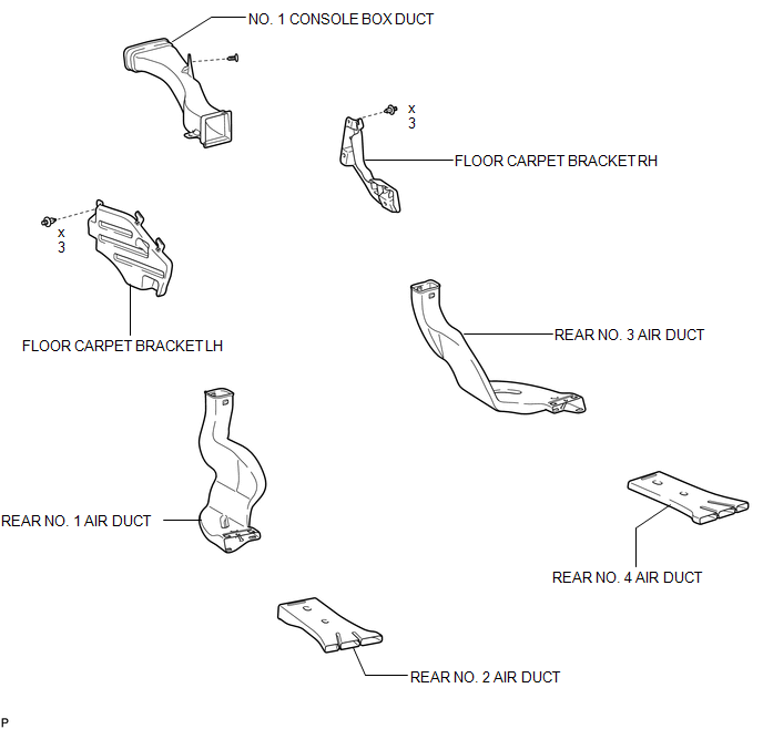
ILLUSTRATION
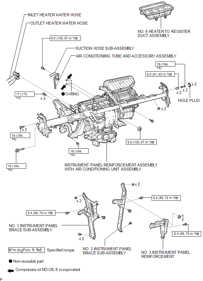
ILLUSTRATION
ILLUSTRATION
ILLUSTRATION
ILLUSTRATION

 Removal
REMOVAL
CAUTION / NOTICE / HINT
NOTICE:
Make sure to select FACE mode before disconnecting the cable from the negative
(-) battery terminal.
PROCEDURE
1. RECOVER REFRIGERANT FROM REFRIGERATION ...
Other materials about Toyota Venza:
Tire Pressure Warning Receiver
Components
COMPONENTS
ILLUSTRATION
Removal
REMOVAL
PROCEDURE
1. DISCONNECT CABLE FROM NEGATIVE BATTERY TERMINAL
NOTICE:
When disconnecting the cable, some systems need to be initialized after the cable
is reconnected (See page ).
2. REMOVE RO ...
Installation
INSTALLATION
CAUTION / NOTICE / HINT
HINT:
Use the same procedure for the RH side and LH side.
The procedure listed below is for the LH side.
PROCEDURE
1. INSTALL REAR AXLE HUB AND BEARING ASSEMBLY
(a) Install the parking bra ...
Removal
REMOVAL
CAUTION / NOTICE / HINT
HINT:
The front side fix window assembly can be reused. When installing the
window, if any of the clips on the front side fix window assembly are broken,
butyl tape can be used to support the glass until the a ...

0.1412