Toyota Venza: Installation
INSTALLATION
PROCEDURE
1. INSTALL SHIFT LEVER ASSEMBLY
NOTICE:
Check that the park/neutral position switch and the shift lever are in neutral.
|
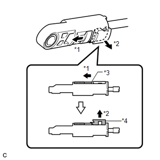
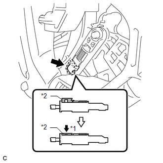
(a) Slide the slider of the transmission control cable in the direction indicated by the arrow and pull the lock piece outward. Text in Illustration
|
|
|
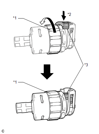
(b) Turn the lock nut of the transmission control cable counterclockwise. While holding the lock nut, push in the stopper. Text in Illustration
|
|
|
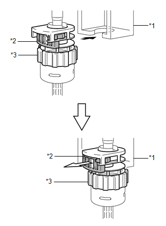
(c) Connect the outer part of the transmission control cable to the shift lever retainer. Text in Illustration
NOTICE: The lock nut is fully seated against the shift lever retainer. |
|
|
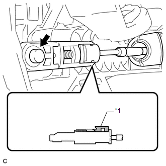
(d) Install the transmission control cable end to the shift lever assembly. Text in Illustration
NOTICE:
|
|
|
(e) Install the shift lever assembly with the 4 nuts. Torque: 12 N·m {122 kgf·cm, 9 ft·lbf} |
|
.png)
(f) Connect the 2 connectors.
|
(g) Push the lock piece into the adjuster case. Text in Illustration
NOTICE: Securely push in the lock piece until the slider lock is engaged. |
|
2. INSTALL CONSOLE BOX SUB-ASSEMBLY
.gif)
3. INSTALL POSITION INDICATOR HOUSING ASSEMBLY
4. INSTALL SHIFT LEVER KNOB SUB-ASSEMBLY
5. INSTALL LOWER INSTRUMENT PANEL SUB-ASSEMBLY
6. INSTALL NO. 2 INSTRUMENT PANEL UNDER COVER SUB-ASSEMBLY
7. INSTALL COWL SIDE TRIM SUB-ASSEMBLY RH
8. INSTALL FRONT DOOR SCUFF PLATE RH
9. INSTALL LOWER NO. 1 INSTRUMENT PANEL FINISH PANEL
10. INSTALL COWL SIDE TRIM SUB-ASSEMBLY LH
11. INSTALL FRONT DOOR SCUFF PLATE LH
12. INSTALL AIR CONDITIONING CONTROL ASSEMBLY
13. INSTALL CONSOLE BOX ASSEMBLY
14. INSTALL NO. 2 CONSOLE BOX CARPET
15. INSTALL UPPER CONSOLE PANEL SUB-ASSEMBLY (w/o Seat Heater System)
16. INSTALL UPPER CONSOLE PANEL SUB-ASSEMBLY (w/ Seat Heater System)
17. CONNECT CABLE TO NEGATIVE BATTERY TERMINAL
NOTICE:
When disconnecting the cable, some systems need to be initialized after the cable
is reconnected (See page ).
18. INSPECT SHIFT LEVER POSITION
19. ADJUST SHIFT LEVER POSITION
 Inspection
INSPECTION
PROCEDURE
1. INSPECT SHIFT LOCK CONTROL UNIT ASSEMBLY (w/o Smart Key System)
(a) Measure the voltage according to the value(s) in the table below.
Text in Illustration
...
 Reassembly
REASSEMBLY
PROCEDURE
1. INSTALL SHIFT LOCK CONTROL COMPUTER SUB-ASSEMBLY
(a) Engage the 3 claws to install the shift lock control computer sub-assembly.
...
Other materials about Toyota Venza:
Adjustment
ADJUSTMENT
PROCEDURE
1. ADJUST STEERING WHEEL OFF CENTER
(a) Inspect steering wheel off center.
(1) Apply masking tape on the top center of the steering wheel and steering
column upper cover.
Text in Illustration
*1
...
Components
COMPONENTS
ILLUSTRATION
ILLUSTRATION
ILLUSTRATION
ILLUSTRATION
ILLUSTRATION
ILLUSTRATION
ILLUSTRATION
ILLUSTRATION
ILLUSTRATION
ILLUSTRATION
...
Transmission Wire(when Using The Engine Support Bridge)
Components
COMPONENTS
ILLUSTRATION
Installation
INSTALLATION
PROCEDURE
1. INSTALL TRANSMISSION WIRE
(a) Coat the O-ring with ATF.
(b) Coat the bolt with ATF.
(c) Install the transmission ...

0.13