Toyota Venza: Inspection
INSPECTION
PROCEDURE
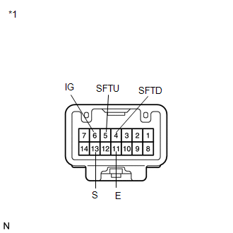
1. INSPECT SHIFT LOCK CONTROL UNIT ASSEMBLY (w/o Smart Key System)
|
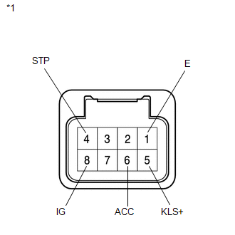
(a) Measure the voltage according to the value(s) in the table below. Text in Illustration
Standard Voltage:
HINT: Do not disconnect the shift lock control unit assembly connector. |
|
|
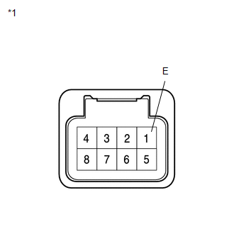
(b) Measure the resistance according to the value(s) in the table below. Text in Illustration
Standard Resistance:
HINT: Do not disconnect the shift lock control unit assembly connector. If the result is not as specified, replace the shift lever assembly. |
|
2. INSPECT SHIFT LOCK CONTROL UNIT ASSEMBLY (w/ Smart Key System)
|
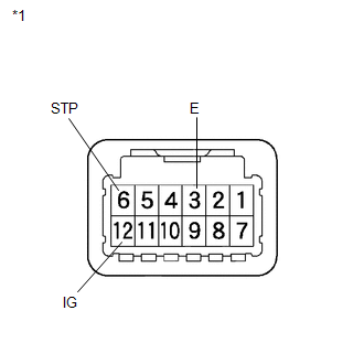
(a) Measure the voltage according to the value(s) in the table below. Text in Illustration
Standard Voltage:
HINT: Do not disconnect the shift lock control unit assembly connector. If the result is not as specified, replace the shift lock control unit assembly. |
|
|
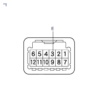
(b) Measure the resistance according to the value(s) in the table below. Text in Illustration
Standard Resistance:
HINT: Do not disconnect the shift lock control unit assembly connector. If the result is not as specified, replace the shift lock control unit assembly. |
|
3. INSPECT TRANSMISSION CONTROL SWITCH
|
(a) Measure the resistance between each terminal of the shift lock control unit assembly when the shift lever is moved to each position. Text in Illustration
Standard Resistance:
If the result is not as specified, replace the shift lock control unit assembly. |
|
4. INSPECT SHIFT LOCK SOLENOID
(a) Disconnect the shift lock solenoid connector.
|
(b) Measure the resistance according to the value(s) in the table below when the shift lever is moved to each position. Text in Illustration
Standard Resistance:
If the result is not as specified, replace the shift lock control unit assembly. |
|
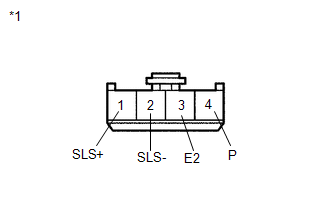
(c) Measure the resistance according to the value(s) in the table below.
Standard Resistance:
|
Tester Connection |
Condition |
Specified Condition |
|---|---|---|
|
1 (SLS+) - 2 (SLS-) |
Always |
112 Ω |
If the result is not as specified, replace the shift lock control unit assembly.
 Removal
REMOVAL
PROCEDURE
1. DISCONNECT CABLE FROM NEGATIVE BATTERY TERMINAL
NOTICE:
When disconnecting the cable, some systems need to be initialized after the cable
is reconnected (See page ).
2. RE ...
 Installation
INSTALLATION
PROCEDURE
1. INSTALL SHIFT LEVER ASSEMBLY
NOTICE:
Check that the park/neutral position switch and the shift lever are in neutral.
(a) Slide the slider of the transmission ...
Other materials about Toyota Venza:
Clearance Warning Buzzer Circuit
DESCRIPTION
This circuit consists of the No. 1 clearance warning buzzer and clearance warning
ECU assembly. An ECU-excited type buzzer is used. The ECU operates the buzzer using
a sound pattern that changes depending on the distance to the obstacle.
WIRI ...
Removal
REMOVAL
PROCEDURE
1. REMOVE REAR DOOR SCUFF PLATE RH
HINT:
Use the same procedure for the RH side and LH side (See page
).
2. DISCONNECT REAR DOOR OPENING TRIM WEATHERSTRIP RH
HINT:
Use the same procedure for the RH side and LH side (See page
).
3. ...
Vehicle Speed Signal Malfunction (B2282)
DESCRIPTION
The power management control ECU receives vehicle speed information using 2 methods.
It receives a speed signal from the meter ECU. It also receives speed information
from the meter ECU via CAN. If the information sent using these 2 methods is ...

0.1186