Toyota Venza: TRAC OFF Indicator Light Remains ON
DESCRIPTION
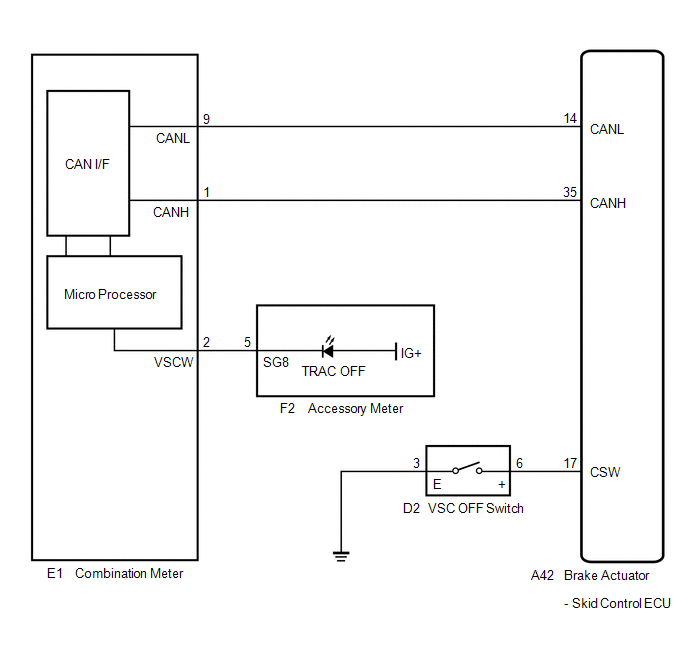
The skid control ECU is connected to the combination meter via CAN communication.
Pressing the VSC OFF switch turns off traction control and pressing and holding this switch turns off traction and VSC controls. If TRAC control is turned off, the TRAC OFF indicator light will come on.
WIRING DIAGRAM
PROCEDURE
|
1. |
CHECK CAN COMMUNICATION SYSTEM |
(a) Check if a CAN communication system DTC is output (See page
.gif) ).
).
|
Result |
Proceed to |
|---|---|
|
DTC is not output |
A |
|
DTC is output |
B |
| B | .gif) |
INSPECT CAN COMMUNICATION SYSTEM |
|
.gif)
|
2. |
CHECK IF SKID CONTROL ECU CONNECTOR IS SECURELY CONNECTED |
(a) Check if the skid control ECU connector is securely connected.
OK:
The connector is securely connected.
| NG | |
CONNECT CONNECTOR TO ECU CORRECTLY |
|
|
3. |
CHECK BATTERY |
(a) Check the battery voltage.
Standard Voltage:
11 to 14 V
|
Result |
Proceed to |
|---|---|
|
OK |
A |
|
NG (for 2GR-FE) |
B |
|
NG (for 1AR-FE) |
C |
| B | |
CHECK OR REPLACE CHARGING SYSTEM OR BATTERY (for 2GR-FE) |
| C | |
CHECK OR REPLACE CHARGING SYSTEM OR BATTERY (for 1AR-FE) |
|
|
4. |
READ VALUE USING TECHSTREAM (VSC OFF SWITCH) |
(a) Connect the Techstream to the DLC3.
(b) Turn the ignition switch to ON.
(c) Select the Data List on the Techstream (See page
).
ABS/VSC/TRAC
|
Tester Display |
Measurement Item/Range |
Normal Condition |
Diagnostic Note |
|---|---|---|---|
|
TRAC/VSC Off Mode |
VSC OFF switch / Normal, TRC OFF, Unknown or VSC OFF |
Normal: Normal mode TRC OFF: TRAC off mode Unknown: Unspecified VSC OFF: VSC off mode |
- |
(d) Using the Techstream, check the switch condition on the Techstream changes according to VSC OFF switch operation.
OK:
The Techstream display changes according to VSC OFF switch operation.
| NG | |
GO TO STEP 6 |
|
|
5. |
INSPECT COMBINATION METER ASSEMBLY |
(a) Turn the ignition switch off.
(b) Turn the ignition switch to ON and check the TRAC OFF indicator light will come on for approximately 3 seconds (initial check).
(c) Perform the Active Test of the combination meter (meter CPU) using the Techstream
(See page ).
(d) Check the accessory meter.
|
Result |
Proceed to |
|---|---|
|
OK |
A |
|
NG (Initial check is normal, and the TRAC OFF indicator light does not turn on or off in accordance with the Techstream operation) |
B |
|
NG (Initial check is abnormal) |
C |
HINT:
If troubleshooting has been carried out according to Problem Symptoms Table,
refer back to the table and proceed to the next step before replacing the part (See
page ).
| A | |
REPLACE BRAKE ACTUATOR ASSEMBLY |
| B | |
REPLACE COMBINATION METER ASSEMBLY |
| C | |
REPLACE ACCESSORY METER ASSEMBLY |
|
6. |
INSPECT VSC OFF SWITCH |
|
(a) Turn the ignition switch off. |
|
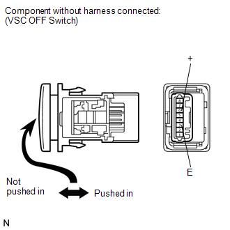
(b) Disconnect the VSC OFF switch connector.
(c) Measure the resistance according to the value(s) in the table below.
Standard Resistance:
|
Tester Connection |
Switch Condition |
Specified Condition |
|---|---|---|
|
6 (+) - 3 (E) |
Switch is pushed in |
Below 1 Ω |
|
6 (+) - 3 (E) |
Switch is not pushed in |
10 kΩ or higher |
| NG | |
REPLACE VSC OFF SWITCH |
|
|
7. |
CHECK HARNESS AND CONNECTOR (SKID CONTROL ECU - VSC OFF SWITCH) |
|
(a) Disconnect the skid control ECU connector. |
|
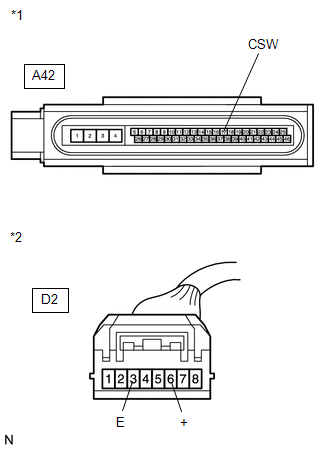
(b) Measure the resistance according to the value(s) in the table below.
Standard Resistance:
|
Tester Connection |
Condition |
Specified Condition |
|---|---|---|
|
A42-17 (CSW) - D2-6 (+) |
Always |
Below 1 Ω |
|
A42-17 (CSW) - Body ground |
Always |
10 kΩ or higher |
|
D2-3 (E) - Body ground |
Always |
Below 1 Ω |
|
*1 |
Front view of wire harness connector (to Brake Actuator (Skid Control ECU)) |
|
*2 |
Front view of wire harness connector (to VSC OFF Switch) |
HINT:
If troubleshooting has been carried out according to Problem Symptoms Table,
refer back to the table and proceed to the next step (See page
).
| OK | |
REPLACE BRAKE ACTUATOR ASSEMBLY |
| NG | |
REPAIR OR REPLACE HARNESS OR CONNECTOR |
 Brake Warning Light does not Come ON
DESCRIPTION
The skid control ECU is connected to the combination meter via CAN communication.
WIRING DIAGRAM
Refer to Brake Warning Light Remains ON (See page
).
PROCEDURE
1.
...
 TRAC OFF Indicator Light does not Come ON
DESCRIPTION
The skid control ECU is connected to the combination meter via CAN communication.
WIRING DIAGRAM
Refer to TRAC OFF Indicator Light Remains ON (See page
).
PROCEDURE
1.
...
Other materials about Toyota Venza:
Microphone Circuit between Microphone and Navigation Receiver Assembly
DESCRIPTION
The navigation receiver assembly and inner rear view mirror assembly
(amplifier microphone assembly) are connected to each other using the microphone
connection detection signal lines.
Using this circuit, the navigation receiver ...
Components
COMPONENTS
ILLUSTRATION
ILLUSTRATION
ILLUSTRATION
ILLUSTRATION
ILLUSTRATION
...
Problem Symptoms Table
PROBLEM SYMPTOMS TABLE
HINT:
Use the table below to help determine the cause of problem symptoms.
If multiple suspected areas are listed, the potential causes of the symptoms
are listed in order of probability in the "Suspected Area" ...

0.1237