Toyota Venza: Installation
INSTALLATION
CAUTION / NOTICE / HINT
HINT:
- Use the same procedure for the RH side and LH side.
- The procedure listed below is for the LH side.
PROCEDURE
1. INSTALL REAR AXLE HUB AND BEARING ASSEMBLY
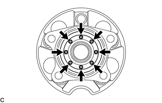
(a) Apply a total of 0.1 to 0.3g (0.00353 to 0.0105 oz.) of Toyota Body Grease W to the 8 areas shown in the illustration.
 Text in Illustration
.png) |
Toyota Body Grease W |
|
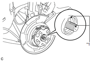
(b) Align the matchmarks on the rear drive shaft assembly and the rear axle hub and bearing assembly. Text in Illustration
NOTICE: Do not rotate the rear drive shaft. |
|
|
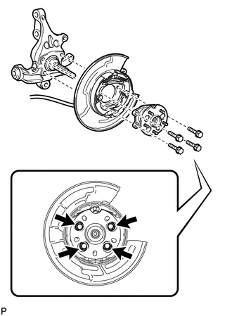
(c) Install the parking brake assembly and the rear axle hub and bearing assembly with the 4 bolts. Torque: 80 N·m {816 kgf·cm, 59 ft·lbf} NOTICE: Do not twist the parking brake cable assembly when installing it. |
|
2. INSTALL REAR AXLE SHAFT NUT
|
(a) Clean the threaded parts on the rear drive shaft assembly and a new rear axle shaft nut using a non-residue solvent. NOTICE:
|
|
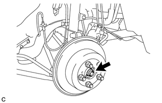
(b) install the rear disc with the 5 hub nuts.
(c) While applying the parking brakes, temporarily install the new rear axle shaft nut.
Torque:
294 N·m {2998 kgf·cm, 217 ft·lbf}
NOTICE:
Stake the nut after inspecting for looseness and runout in the following steps.
(d) Remove the 5 hub nuts and the rear disc.
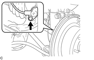
3. INSTALL REAR SPEED SENSOR
|
(a) Install the rear speed sensor to the rear axle carrier sub-assembly with the bolt. Torque: 8.5 N·m {87 kgf·cm, 75 in·lbf} NOTICE:
|
|
4. INSPECT REAR AXLE HUB BEARING LOOSENESS
.gif)
5. INSPECT REAR AXLE HUB RUNOUT
6. INSTALL REAR DISC
7. INSTALL REAR DISC BRAKE CALIPER ASSEMBLY
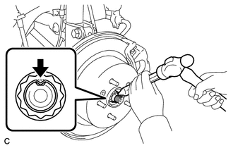
8. STAKE REAR AXLE SHAFT NUT
|
(a) Using a chisel and a hammer, stake the rear axle shaft nut. |
|
9. INSTALL REAR WHEEL
Torque:
103 N·m {1050 kgf·cm, 76 ft·lbf}
10. CHECK FOR SPEED SENSOR SIGNAL
(a) Check for the speed sensor signal (See page
).
 On-vehicle Inspection
ON-VEHICLE INSPECTION
CAUTION / NOTICE / HINT
HINT:
Use the same procedure for the RH side and LH side.
The procedure listed below is for the LH side.
PROCEDURE
1. REMOVE REAR W ...
 Removal
REMOVAL
CAUTION / NOTICE / HINT
HINT:
Use the same procedure for the RH side and LH side.
The procedure listed below is for the LH side.
PROCEDURE
1. REMOVE REAR WHEEL
2. SEPAR ...
Other materials about Toyota Venza:
Stereo Component Amplifier Malfunction (B15A3)
DESCRIPTION
This DTC is stored when a malfunction occurs in the stereo component amplifier
assembly.
DTC No.
DTC Detection Condition
Trouble Area
B15A3
When any of the following conditions is met ...
XM Tuner Malfunction (B15BA)
DESCRIPTION
This DTC is stored when a malfunction occurs in the stereo component tuner assembly.
DTC No.
DTC Detection Condition
Trouble Area
B15BA
When either of the following conditions is met:
...
Inspection
INSPECTION
PROCEDURE
1. INSPECT SPIRAL CABLE
(a) Visually check for defects with the spiral cable removed from the vehicle.
(1) The defects are as follows:
Scratches on the spiral cable
Small cracks the spiral cable
Dents on the spiral cabl ...

0.1542