Toyota Venza: Removal
REMOVAL
CAUTION / NOTICE / HINT
HINT:
- Use the same procedure for the RH side and LH side.
- The procedure listed below is for the LH side.
PROCEDURE
1. REMOVE REAR WHEEL
2. SEPARATE REAR SPEED SENSOR
|
(a) Remove the bolt and separate the rear speed sensor from the rear axle carrier sub-assembly. NOTICE: Keep the sensor tip and rear speed sensor installation hole free of foreign matter. |
|
.png)
3. REMOVE REAR AXLE SHAFT NUT
.gif)
4. SEPARATE REAR DISC BRAKE CALIPER ASSEMBLY
5. REMOVE REAR DISC
6. REMOVE REAR AXLE HUB AND BEARING ASSEMBLY
|
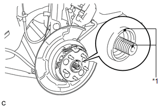
(a) Put matchmarks on the rear drive shaft assembly and rear axle hub and bearing assembly. Text in Illustration
NOTICE: Do not punch the matchmarks. |
|
|
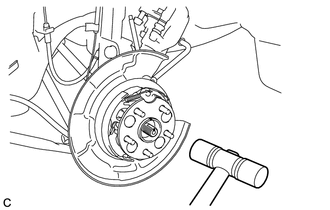
(b) Using a plastic hammer, separate the rear drive shaft assembly from the axle hub and bearing assembly. If it is difficult to separate, tap the end of the rear drive shaft assembly using a brass bar and a hammer. |
|
|
(c) Remove the 4 bolts and the rear axle hub and bearing assembly. NOTICE:
|
|
.png)
 Installation
INSTALLATION
CAUTION / NOTICE / HINT
HINT:
Use the same procedure for the RH side and LH side.
The procedure listed below is for the LH side.
PROCEDURE
1. INSTALL REAR AXLE HUB ...

Other materials about Toyota Venza:
Disposal
DISPOSAL
CAUTION / NOTICE / HINT
HINT:
The tire pressure warning valve and transmitter is powered by a lithium battery.
When disposing of the tire pressure warning valve and transmitter, remove the battery
and dispose of it correctly.
PROCEDURE
1. DIS ...
Reassembly
REASSEMBLY
PROCEDURE
1. INSTALL FRONT SEAT WIRE RH (for Front Passenger Side)
(a) Engage each clamp and install the front seat wire RH.
2. INSTALL OCCUPANT CLASSIFICATION ECU (for Front Passenger Side)
3. INSTALL SEAT POSITION SENSOR
4. INSTALL SEA ...
Customize Parameters
CUSTOMIZE PARAMETERS
HINT:
The following items can be customized.
NOTICE:
After confirming whether the items requested by the customer are applicable
or not for customization, perform customizing operations.
Be sure to record the current se ...

0.1637