Toyota Venza: Short in Driver Side Squib 2nd Step Circuit (B1810/53-B1813/53)
DESCRIPTION
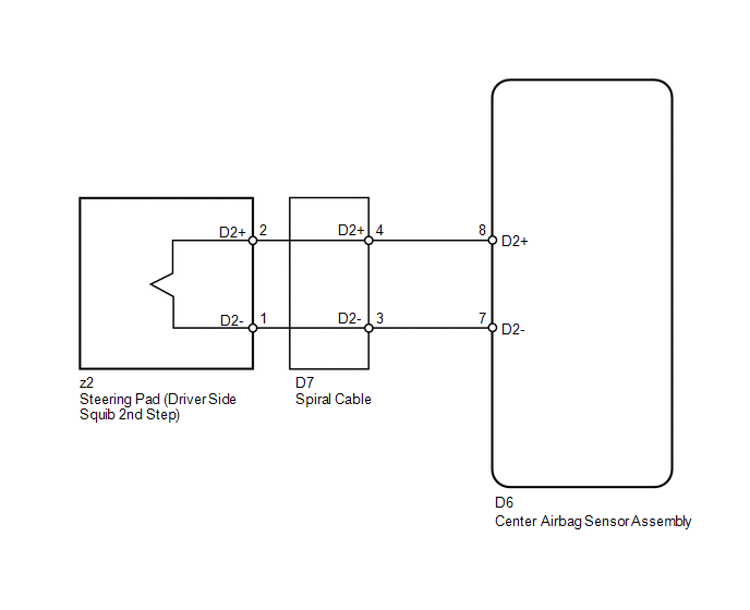
The driver side squib 2nd step circuit consists of the center airbag sensor assembly, spiral cable and steering pad.
The center airbag sensor assembly uses this circuit to deploy the airbag when deployment conditions are met.
These DTCs are stored when a malfunction is detected in the driver side squib 2nd step circuit.
|
DTC No. |
DTC Detection Condition |
Trouble Area |
|---|---|---|
|
B1810/53 |
|
|
|
B1811/53 |
|
|
|
B1812/53 |
|
|
|
B1813/53 |
|
|
WIRING DIAGRAM
CAUTION / NOTICE / HINT
HINT:
- Perform the simulation method by selecting check mode (Signal Check)
using the Techstream (See page
.gif) ).
).
- After selecting check mode (Signal Check), perform the simulation method
by wiggling each connector of the airbag system or driving the vehicle on
a city or rough road (See page ).
PROCEDURE
|
1. |
CHECK CONNECTORS |
|
(a) Turn the ignition switch off. |
|
.png)
(b) Disconnect the cable from the negative (-) battery terminal, and wait for at least 90 seconds.
(c) Check that the connectors are properly connected to the steering pad, spiral cable and center airbag sensor assembly.
OK:
The connectors are properly connected.
HINT:
If the connectors are not connected securely, reconnect the connectors and proceed to the next inspection.
(d) Disconnect the connectors from the steering pad, spiral cable and center airbag sensor assembly.
(e) Check that the terminals of the connectors are not damaged.
OK:
The terminals are not deformed or damaged.
(f) Check that the spiral cable connector (on the steering pad side) is not damaged.
OK:
The lock button is not disengaged, and the claw of the lock is not deformed or damaged.
(g) Check that the short springs for the instrument panel wire and spiral cable with the activation prevention mechanism are not deformed or damaged.
OK:
The short springs are not deformed or damaged.
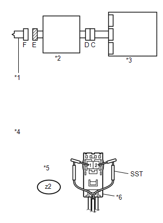
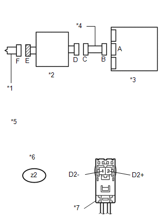
Text in Illustration|
*1 |
Driver Side Squib 2nd Step |
|
*2 |
Spiral Cable |
|
*3 |
Center Airbag Sensor Assembly |
|
*4 |
Instrument Panel Wire |
| NG | .gif) |
REPLACE WIRE HARNESS |
|
.gif)
|
2. |
CHECK STEERING PAD (DRIVER SIDE SQUIB 2ND STEP) |
|
(a) Connect the instrument panel wire to the center airbag sensor assembly and spiral cable. |
|
(b) Connect SST (resistance 2.1 Ω) to connector E (black connector).
CAUTION:
Never connect an electrical tester to the steering pad (driver side squib 2nd step) for measurement, as this may lead to a serious injury due to airbag deployment.
NOTICE:
- Do not forcibly insert SST into the terminals of the connector when connecting.
- Insert SST straight into the terminals of the connector.
SST: 09843-18061
(c) Connect the cable to the negative (-) battery terminal.
(d) Turn the ignition switch to ON, and wait for at least 60 seconds.
(e) Clear the DTCs stored in memory (See page
).
(f) Turn the ignition switch off.
(g) Turn the ignition switch to ON, and wait for at least 60 seconds.
(h) Check for DTCs (See page ).
OK:
DTCs B1810, B1811, B1812, B1813 or 53 is not output.
Text in Illustration|
*1 |
Driver Side Squib 2nd Step |
|
*2 |
Spiral Cable |
|
*3 |
Center Airbag Sensor Assembly |
|
*4 |
Front view of wire harness connector (to Steering Pad) |
|
*5 |
Connector E |
|
*6 |
Color: Black |
HINT:
Codes other than DTCs B1810, B1811, B1812, B1813 and 53 may be output at this time, but they are not related to this check.
| OK | |
REPLACE STEERING PAD |
|
|
3. |
CHECK DRIVER SIDE SQUIB 2ND STEP CIRCUIT |
|
(a) Turn the ignition switch off. |
|
(b) Disconnect the cable from the negative (-) battery terminal, and wait for at least 90 seconds.
(c) Disconnect SST from connector E.
(d) Disconnect the instrument panel wire from the center airbag sensor assembly.
(e) Check for a short to B+ in the circuit.
(1) Connect the cable to the negative (-) battery terminal.
(2) Turn the ignition switch to ON.
(3) Measure the voltage according to the value(s) in the table below.
Standard Voltage:
|
Tester Connection |
Switch Condition |
Specified Condition |
|---|---|---|
|
z2-2 (D2+) - Body ground |
Ignition switch ON |
Below 1 V |
|
z2-1 (D2-) - Body ground |
Ignition switch ON |
Below 1 V |
(f) Check for an open in the circuit.
(1) Turn the ignition switch off.
(2) Disconnect the cable from the negative (-) battery terminal, and wait for at least 90 seconds.
(3) Measure the resistance according to the value(s) in the table below.
Standard Resistance:
|
Tester Connection |
Condition |
Specified Condition |
|---|---|---|
|
z2-2 (D2+) - z2-1 (D2-) |
Always |
Below 1 Ω |
(g) Check for a short to ground in the circuit.
(1) Measure the resistance according to the value(s) in the table below.
Standard Resistance:
|
Tester Connection |
Condition |
Specified Condition |
|---|---|---|
|
z2-2 (D2+) - Body ground |
Always |
1 MΩ or higher |
|
z2-1 (D2-) - Body ground |
Always |
1 MΩ or higher |
(h) Check for a short in the circuit.
(1) Release the activation prevention mechanism built into connector B (See page
).
(2) Measure the resistance according to the value(s) in the table below.
Standard Resistance:
|
Tester Connection |
Condition |
Specified Condition |
|---|---|---|
|
z2-2 (D2+) - z2-1 (D2-) |
Always |
1 MΩ or higher |
|
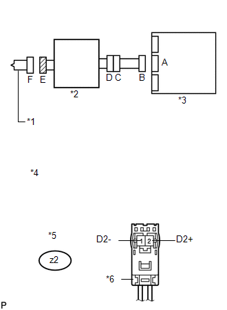
*1 |
Driver Side Squib 2nd Step |
|
*2 |
Spiral Cable |
|
*3 |
Center Airbag Sensor Assembly |
|
*4 |
Front view of wire harness connector (to Steering Pad) |
|
*5 |
Connector E |
|
*6 |
Color: Black |
| NG | |
GO TO STEP 5 |
|
|
4. |
CHECK CENTER AIRBAG SENSOR ASSEMBLY |
|
(a) Restore the released activation prevention mechanism of connector B to the original condition. |
|
.png)
(b) Connect the connectors to the steering pad and center airbag sensor assembly.
(c) Connect the cable to the negative (-) battery terminal.
(d) Turn the ignition switch to ON, and wait for at least 60 seconds.
(e) Clear the DTCs stored in memory (See page
).
(f) Turn the ignition switch off.
(g) Turn the ignition switch to ON, and wait for at least 60 seconds.
(h) Check for DTCs (See page ).
OK:
DTC B1810, B1811, B1812, B1813 or 53 is not output.
Text in Illustration|
*1 |
Driver Side Squib 2nd Step |
|
*2 |
Spiral Cable |
|
*3 |
Center Airbag Sensor Assembly |
HINT:
Codes other than DTCs B1810, B1811, B1812, B1813 and 53 may be output at this time, but they are not related to this check.
| OK | |
USE SIMULATION METHOD TO CHECK |
| NG | |
REPLACE CENTER AIRBAG SENSOR ASSEMBLY |
|
5. |
CHECK INSTRUMENT PANEL WIRE |
|
(a) Restore the release activation prevention mechanism of connector B to the original condition. |
|
(b) Disconnect the instrument panel wire from spiral cable.
(c) Check for a short to B+ in the circuit.
(1) Connect the cable to the negative (-) battery terminal.
(2) Turn the ignition switch to ON.
(3) Measure the voltage according to the value(s) in the table below.
Standard Voltage:
|
Tester Connection |
Switch Condition |
Specified Condition |
|---|---|---|
|
D7-4 (D2+) - Body ground |
Ignition switch ON |
Below 1 V |
|
D7-3 (D2-) - Body ground |
Ignition switch ON |
Below 1 V |
(d) Check for an open in the circuit.
(1) Turn the ignition switch off.
(2) Disconnect the cable from the negative (-) battery terminal, and wait for at least 90 seconds.
(3) Measure the resistance according to the value(s) in the table below.
Standard Resistance:
|
Tester Connection |
Condition |
Specified Condition |
|---|---|---|
|
D7-4 (D2+) - D7-3 (D2-) |
Always |
Below 1 Ω |
(e) Check for a short to ground in the circuit.
(1) Measure the resistance according to the value(s) in the table below.
Standard Resistance:
|
Tester Connection |
Condition |
Specified Condition |
|---|---|---|
|
D7-4 (D2+) - Body ground |
Always |
1 MΩ or higher |
|
D7-3 (D2-) - Body ground |
Always |
1 MΩ or higher |
(f) Check for a short in the circuit.
(1) Release the activation prevention mechanism built into connector B (See page
).
(2) Measure the resistance according to the value(s) in the table below.
Standard Resistance:
|
Tester Connection |
Condition |
Specified Condition |
|---|---|---|
|
D7-4 (D2+) - D7-3 (D2-) |
Always |
1 MΩ or higher |
|
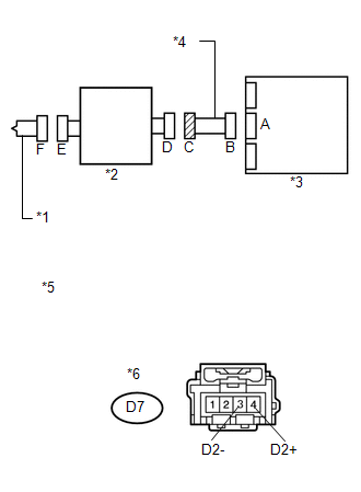
*1 |
Driver Side Squib 2nd Step |
|
*2 |
Spiral Cable |
|
*3 |
Center Airbag Sensor Assembly |
|
*4 |
Instrument Panel Wire |
|
*5 |
Front view of wire harness connector (to Spiral Cable) |
|
*6 |
Connector C |
| NG | |
REPLACE INSTRUMENT PANEL WIRE |
|
|
6. |
CHECK SPIRAL CABLE |
|
(a) Check for a short to B+ in the circuit. (1) Connect the cable to the negative (-) battery terminal. (2) Turn the ignition switch to ON. (3) Measure the voltage according to the value(s) in the table below. Standard Voltage:
|
|
(b) Check for an open in the circuit.
(1) Turn the ignition switch off.
(2) Disconnect the cable from the negative (-) battery terminal, and wait for at least 90 seconds.
(3) Measure the resistance according to the value(s) in the table below.
Standard Resistance:
|
Tester Connection |
Condition |
Specified Condition |
|---|---|---|
|
z2-2 (D2+) - z2-1 (D2-) |
Always |
Below 1 Ω |
(c) Check for a short to ground in the circuit.
(1) Measure the resistance according to the value(s) in the table below.
Standard Resistance:
|
Tester Connection |
Condition |
Specified Condition |
|---|---|---|
|
z2-2 (D2+) - Body ground |
Always |
1 MΩ or higher |
|
z2-1 (D2-) - Body ground |
Always |
1 MΩ or higher |
(d) Check for a short in the circuit.
(1) Release the activation prevention mechanism built into connector D (See page
).
(2) Measure the resistance according to the value(s) in the table below.
Standard Resistance:
|
Tester Connection |
Condition |
Specified Condition |
|---|---|---|
|
z2-2 (D2+) - z2-1 (D2-) |
Always |
1 MΩ or higher |
|
*1 |
Driver Side Squib 2nd Step |
|
*2 |
Spiral Cable |
|
*3 |
Center Airbag Sensor Assembly |
|
*4 |
Instrument Panel Wire |
|
*5 |
Front view of wire harness connector (to Steering Pad) |
|
*6 |
Connector E |
|
*7 |
Color: Black |
| OK | |
USE SIMULATION METHOD TO CHECK |
| NG | |
REPLACE SPIRAL CABLE |
 Short in Front Passenger Side Squib Circuit (B1805/52-B1808/52)
DESCRIPTION
The front passenger side squib circuit consists of the center airbag sensor assembly
and front passenger airbag assembly.
The center airbag sensor assembly uses this circuit to deploy ...
 Short in Front Passenger Side Squib 2nd Step Circuit (B1815/54-B1818/54)
DESCRIPTION
The front passenger side squib 2nd step circuit consists of the center airbag
sensor assembly and front passenger airbag assembly.
The center airbag sensor assembly uses this circuit t ...
Other materials about Toyota Venza:
Installation
INSTALLATION
CAUTION / NOTICE / HINT
HINT:
Perform "Inspection After Repair" after replacing the engine assembly (See page
).
PROCEDURE
1. INSTALL IGNITION COIL ASSEMBLY
2. INSTALL FUEL DELIVERY PIPE SUB-ASSEMBLY
3. INSTALL ENGINE COOL ...
Problem Symptoms Table
PROBLEM SYMPTOMS TABLE
HINT:
Use the table below to help determine the cause of problem symptoms.
If multiple suspected areas are listed, the potential causes of the symptoms
are listed in order of probability in the "Suspected Area" ...
Key-off Operation Function Operates even if Operating Conditions are not Satisfied
DESCRIPTION
When the front doors are closed, each power window regulator motor assembly
can control its power window operation for approximately 45 seconds after
the ignition switch is turned from ON to off by receiving operation permission
...

0.1611