Toyota Venza: Removal
REMOVAL
PROCEDURE
1. REMOVE REAR BUMPER ASSEMBLY
(See page .gif) )
)
2. REMOVE ULTRASONIC SENSOR CLIP
|
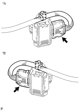
(a) Disconnect the connector. Text in Illustration
|
|
(b) Disengage the clamp.
|
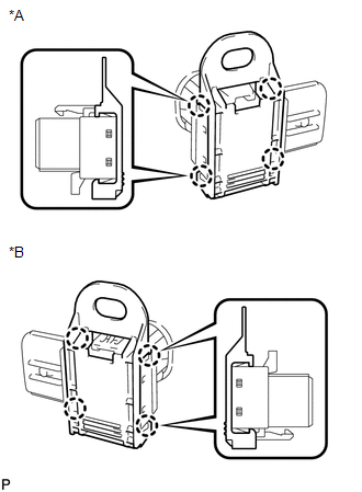
(c) Disengage the 4 claws to remove the ultrasonic sensor clip. Text in Illustration
|
|
3. REMOVE NO. 1 ULTRASONIC SENSOR
|
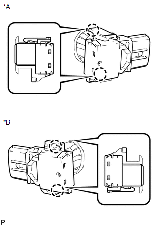
(a) Disengage the 2 claws to remove the No. 1 ultrasonic sensor. Text in Illustration
|
|
4. REMOVE NO. 1 ULTRASONIC SENSOR RETAINER
|
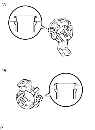
(a) Disengage the 2 claws to remove the No. 1 ultrasonic sensor retainer from the rear bumper assembly. Text in Illustration
|
|
 Inspection
INSPECTION
PROCEDURE
1. INSPECT NO. 1 ULTRASONIC SENSOR
(a) Measure the resistance according to the value(s) in the table below.
Standard Resistance:
Tester Conne ...
 Installation
INSTALLATION
PROCEDURE
1. INSTALL NO. 1 ULTRASONIC SENSOR RETAINER
(a) Engage the 2 claws to install the No. 1 ultrasonic sensor retainer
to the rear bumper assembly.
Text in Illu ...
Other materials about Toyota Venza:
Tcm
Components
COMPONENTS
ILLUSTRATION
Removal
REMOVAL
CAUTION / NOTICE / HINT
NOTICE:
If automatic transmission parts are replaced, refer to Parts Replacement Compensation
Table to determine if any additional operations are necessary (See page
). ...
Front Sensor Communication Malfunction (C1AEC)
DESCRIPTION
This DTC is stored when there is an open or short circuit in the communication
line between the front sensors and the ECU, or when there is a malfunction in a
front sensor.
DTC No.
DTC Detection Condition
Trou ...
Air Conditioning Amplifier
Components
COMPONENTS
ILLUSTRATION
Installation
INSTALLATION
PROCEDURE
1. INSTALL AIR CONDITIONING AMPLIFIER ASSEMBLY
(a) Install the air conditioning amplifier assembly with the 2 screws.
...

0.1298