Toyota Venza: Removal
REMOVAL
PROCEDURE
1. REMOVE REAR WHEELS
2. REMOVE CENTER EXHAUST PIPE ASSEMBLY
(a) Remove the center exhaust pipe assembly.
HINT:
Refer to the instructions for Removal of the exhaust pipe (See page
.gif) for 2GR-FE,
for 2GR-FE,
for 1AR-FE).
3. REMOVE PROPELLER WITH CENTER BEARING SHAFT ASSEMBLY
4. SEPARATE REAR HEIGHT CONTROL SENSOR SUB-ASSEMBLY (w/ HID Headlight System)
|
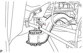
(a) Remove the nut and separate the rear height control sensor sub-assembly from the rear No. 2 suspension arm assembly RH. NOTICE: Use wire or an equivalent tool to keep the rear height control sensor link from hanging down. |
|
.png)
5. SEPARATE NO. 3 PARKING BRAKE CABLE ASSEMBLY
6. SEPARATE NO. 2 PARKING BRAKE CABLE ASSEMBLY
HINT:
Perform the same procedure as the LH side.
7. REMOVE REAR STRUT ROD ASSEMBLY LH
8. REMOVE REAR STRUT ROD ASSEMBLY RH
HINT:
Perform the same procedure as the LH side.
9. REMOVE REAR NO. 2 SUSPENSION ARM ASSEMBLY LH
|
(a) Put matchmarks on the adjust cams and the rear suspension member sub-assembly. Text in Illustration
|
|
.png)
(b) Remove the bolt (A) and the nut, and separate the rear No. 2 suspension arm assembly LH from the rear axle carrier sub-assembly LH.
NOTICE:
Since a stopper nut is used, loosen the bolt.
(c) Remove the nut (B), the No. 2 camber adjust cam, the rear suspension toe adjust cam sub-assembly, and the rear No. 2 suspension arm assembly LH.
HINT:
When removing the nut, keep the rear suspension toe adjust cam sub-assembly from rotating.
10. REMOVE REAR NO. 2 SUSPENSION ARM ASSEMBLY RH
HINT:
Perform the same procedure as the LH side.
11. SEPARATE REAR NO. 1 SUSPENSION ARM ASSEMBLY LH
|
(a) Remove the bolt and the nut, and separate the rear No. 1 suspension arm assembly LH from the rear axle carrier sub-assembly LH. NOTICE: Since a stopper nut is used, loosen the bolt. |
|
.png)
12. SEPARATE REAR NO. 1 SUSPENSION ARM ASSEMBLY RH
HINT:
Perform the same procedure as the LH side.
13. REMOVE NO. 1 FLOOR UNDER COVER
|
(a) Separate the 5 clips to remove the No. 1 floor under cover. HINT: Remove the No. 1 floor under cover with the 5 clips. |
|
.png)
14. SEPARATE FRAME WIRE
|
(a) Disengage the 2 clamps to separate the frame wire from the body. |
|
.png)
15. SEPARATE NO. 3 FLOOR WIRE (w/ HID Headlight System)
|
(a) Disconnect the connector and disengage the clamp to separate the No. 3 floor wire from the rear suspension member. |
|
.png)
16. SEPARATE REAR SUSPENSION MEMBER
|
(a) Support the rear suspension member with a jack using 3 wooden blocks as shown in the illustration. Text in Illustration
HINT: Use properly sized wooden blocks to keep the jack and suspension member level. |
|
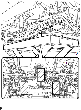
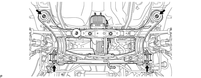
(b) Remove the 4 nuts, 2 bolts and 2 rear lower suspension member stopper retainers.
|
(c) Lower the rear suspension member to the point shown in the illustration. Length (A): 100 mm (3.94 in.) |
|
17. REMOVE REAR NO. 1 SUSPENSION ARM ASSEMBLY LH
|
(a) Remove the bolt, the nut and the rear No. 1 suspension arm assembly LH from the rear suspension member. NOTICE: Since a stopper nut is used, loosen the bolt. |
|
.png)
18. REMOVE REAR NO. 1 SUSPENSION ARM ASSEMBLY RH
HINT:
Perform the same procedure as the LH side.
 Installation
INSTALLATION
PROCEDURE
1. INSTALL REAR NO. 1 SUSPENSION ARM ASSEMBLY LH
(a) Temporarily install the rear No. 1 suspension arm assembly LH to
the rear suspension member with the bolt ...

Other materials about Toyota Venza:
Horn Circuit
DESCRIPTION
When the theft deterrent system is switched from the armed state to the alarm
sounding state, the main body ECU (driver side junction block assembly) transmits
a signal to cause the horn to sound at intervals of 0.4 seconds.
WIRING DIAGRAM
...
Front Stabilizer Bar(for 2gr-fe 2wd)
Components
COMPONENTS
ILLUSTRATION
Removal
REMOVAL
PROCEDURE
1. REMOVE FRONT FRAME ASSEMBLY (When Using the Engine Support Bridge)
(See page )
2. REMOVE ENGINE ASSEMBLY WITH TRANSAXLE (When Not Using the Engine Support Bridge)
(See page )
3. ...
Transponder Key Ecu
Components
COMPONENTS
ILLUSTRATION
Removal
REMOVAL
PROCEDURE
1. REMOVE AIR CONDITIONING UNIT ASSEMBLY
HINT:
Refer to the procedure up to Remove Air Conditioning Unit Assembly (See page
).
2. REMOVE TRANSPONDER KEY ECU ASSEMBLY
(a) ...

0.1406