Toyota Venza: Installation
INSTALLATION
PROCEDURE
1. INSTALL NO. 3 ANTENNA CORD SUB-ASSEMBLY
(a) Pass the washer hose through the No. 3 antenna cord sub-assembly.
|
(b) Pass the No. 3 antenna cord sub-assembly with washer hose through the vehicle body as shown in the illustration. |
|
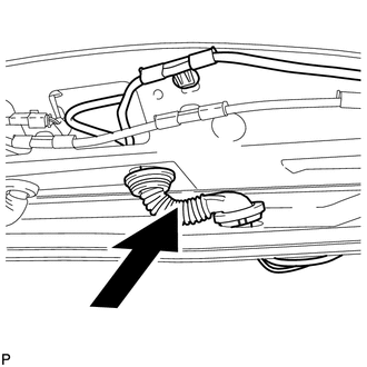
(c) Engage the 2 claws.
(d) Connect the grommet to the back door.
(e) Engage the 4 clamps.
.png) Text in Illustration
Text in Illustration
|
*1 |
Clamp |
*2 |
Grommet |
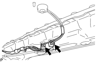
(f) Connect the connector and engage the clamp.
(g) w/o Satellite Radio:
(1) Engage the 7 clamps.
(2) Engage the 4 hooks to connect the washer hose.
.png) Text in Illustration
Text in Illustration
|
*1 |
Clamp |
*2 |
Hook |
|
*3 |
Washer Hose |
- |
- |
|
(3) Connect the 2 connectors. |
|
(h) w/ Satellite Radio:
(1) Engage the 5 clamps.
(2) Engage the 4 hooks to connect the washer hose.
.png) Text in Illustration
Text in Illustration
|
*1 |
Clamp |
*2 |
Hook |
|
*3 |
Washer Hose |
- |
- |
(3) Connect the connector.
|
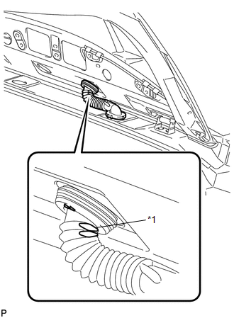
(i) Set the position of the grommet as shown in the illustration. Text in Illustration
HINT: Flat area to be oriented outside the vehicle. |
|
2. INSTALL BACK DOOR TRIM COVER RH
.gif)
3. INSTALL BACK DOOR TRIM COVER LH (w/o Power Back Door)
4. INSTALL BACK DOOR TRIM COVER LH (w/ Power Back Door)
5. INSTALL BACK DOOR PANEL TRIM ASSEMBLY
6. INSTALL UPPER BACK WINDOW PANEL TRIM
7. INSTALL NO. 2 ANTENNA CORD SUB-ASSEMBLY (w/o Sliding Roof)
(a) Aligning the No. 2 antenna cord sub-assembly and washer hose with the markings on the roof headlining assembly, temporarily install the cord and washer hose.
.png) Text in Illustration
Text in Illustration
.png) |
Tape |
- |
- |
.png) |
Front |
- |
- |
(b) Put the strips of the tape back to the positions shown in the illustration in order to secure the antenna cord and washer hose to the roof headlining assembly.
HINT:
- If the tape has lost adhesion, use other tape, such as packing tape, with enough adhesion to secure the antenna cord and washer hose to the roof headlining assembly.
- Secure the antenna cord and washer hose to the roof headlining assembly with tape as shown in the illustration.
8. INSTALL NO. 2 ANTENNA CORD SUB-ASSEMBLY (w/ Sliding Roof)
(a) Aligning the No. 2 antenna cord sub-assembly and washer hose with the markings on the roof headlining assembly, temporarily install the cord and washer hose.
.png) Text in Illustration
Text in Illustration
|
|
Tape |
- |
- |
|
|
Front |
- |
- |
(b) Put the strips of the tape back to the positions shown in the illustration in order to secure the antenna cord and washer hose to the roof headlining assembly.
HINT:
- If the tape has lost adhesion, use other tape, such as packing tape, with enough adhesion to secure the antenna cord and washer hose to the roof headlining assembly.
- Secure the antenna cord and washer hose to the roof headlining assembly with tape as shown in the illustration.
9. INSTALL ROOF HEADLINING ASSEMBLY
(See page )
10. INSTALL NO. 1 ANTENNA CORD SUB-ASSEMBLY
(a) Engage the 7 clamps to install the No. 1 antenna cord sub-assembly.
.png)
11. INSTALL INSTRUMENT PANEL SAFETY PAD ASSEMBLY
(See page )
 Removal
REMOVAL
PROCEDURE
1. REMOVE INSTRUMENT PANEL SAFETY PAD ASSEMBLY
(See page )
2. REMOVE NO. 1 ANTENNA CORD SUB-ASSEMBLY
(a) Disengage the 7 clamps and remove the No. 1 antenna cord sub-assembly.
...
 Radio Antenna Pole
Components
COMPONENTS
ILLUSTRATION
Removal
REMOVAL
PROCEDURE
1. REMOVE ROOF ANTENNA POLE SUB-ASSEMBLY
(a) Turn the roof antenna pole sub-assembly in the direction indicated
...
Other materials about Toyota Venza:
Front Occupant Classification Sensor RH Circuit Malfunction (B1781)
DESCRIPTION
The front occupant classification sensor RH circuit consists of the occupant
classification ECU and front occupant classification sensor RH.
DTC B1781 is recorded when a malfunction is detected in the front occupant classification
sensor RH c ...
Glossary Of Sae And Toyota Terms
GLOSSARY OF SAE AND TOYOTA TERMS
This glossary lists all SAE-J1930 terms and abbreviations used in this manual
in compliance with SAE recommendations, as well as their TOYOTA equivalents.
SAE
Abbreviation
SAE Term
TOYOTA ...
How To Proceed With Troubleshooting
CAUTION / NOTICE / HINT
HINT:
Use the following procedure to troubleshoot the front power seat control
system (w/ Memory).
*: Use the Techstream.
PROCEDURE
1.
VEHICLE BROUGHT TO WORKSHOP
...

0.1228