Toyota Venza: Radio Antenna Pole
Components
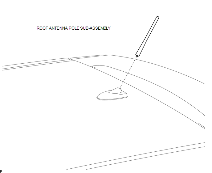
COMPONENTS
ILLUSTRATION
Removal
REMOVAL
PROCEDURE
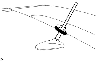
1. REMOVE ROOF ANTENNA POLE SUB-ASSEMBLY
|
(a) Turn the roof antenna pole sub-assembly in the direction indicated by the arrow in the illustration to remove it. |
|
Installation
INSTALLATION
PROCEDURE
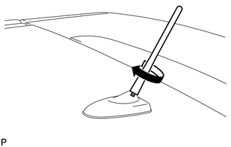
1. INSTALL ROOF ANTENNA POLE SUB-ASSEMBLY
|
(a) Turn the roof antenna pole sub-assembly in the direction indicated by the arrow in the illustration to install it. |
|
 Installation
INSTALLATION
PROCEDURE
1. INSTALL NO. 3 ANTENNA CORD SUB-ASSEMBLY
(a) Pass the washer hose through the No. 3 antenna cord sub-assembly.
(b) Pass the No. 3 antenna cord sub-assembly with ...
 Radio Receiver
...
Other materials about Toyota Venza:
Camshaft Position "A" - Timing Over-Advanced or System Performance (Bank 1)
(P0011,P0012)
DESCRIPTION
Refer to DTC P0010 (See page ).
DTC No.
DTC Detection Condition
Trouble Area
P0011
The valve timing is stuck at a certain value when in the advance range
(1 trip detection logic).
...
Removal
REMOVAL
PROCEDURE
1. REMOVE ENGINE ASSEMBLY WITH TRANSAXLE
(a) Remove the engine and transaxle (See page
).
2. REMOVE EXHAUST MANIFOLD CONVERTER SUB-ASSEMBLY
(a) Remove the exhaust manifold converter (See page
).
3. REMOVE THROTTLE BODY ASSEMBLY
...
Diagnostic Trouble Code Chart
DIAGNOSTIC TROUBLE CODE CHART
If a trouble code is displayed during the DTC check, check the circuit listed
for the code in the table below (proceed to the page listed for that circuit).
HINT:
When DTC B1650/32 is detected as a result of troubleshooting f ...

0.1291