Toyota Venza: Removal
REMOVAL
PROCEDURE
1. REMOVE INSTRUMENT PANEL SAFETY PAD ASSEMBLY
(See page .gif) )
)
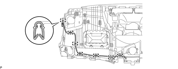
2. REMOVE NO. 1 ANTENNA CORD SUB-ASSEMBLY
(a) Disengage the 7 clamps and remove the No. 1 antenna cord sub-assembly.
3. REMOVE ROOF HEADLINING ASSEMBLY
(See page )
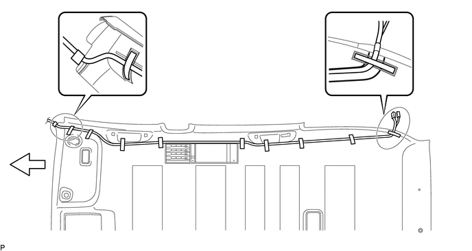
4. REMOVE NO. 2 ANTENNA CORD SUB-ASSEMBLY (w/o Sliding Roof)
(a) Peel up the strips of tape so that the washer hose and No. 2 antenna cord sub-assembly can be removed.
 Text in Illustration
 |
Tape |
- |
- |
 |
Front |
- |
- |
HINT:
Tape is not available as a supply part. Try to leave as much tape as possible on the roof headlining so that the tape can be reused.
(b) Remove the washer hose and No. 2 antenna cord sub-assembly from the roof headlining assembly.
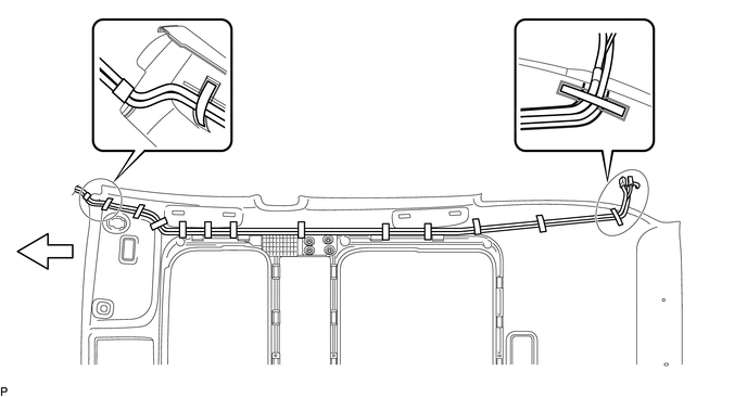
5. REMOVE NO. 2 ANTENNA CORD SUB-ASSEMBLY (w/ Sliding Roof)
(a) Peel up the strips of tape so that the washer hose and No. 2 antenna cord sub-assembly can be removed.
 Text in Illustration
|
|
Tape |
- |
- |
|
|
Front |
- |
- |
HINT:
Tape is not available as a supply part. Try to leave as much tape as possible on the roof headlining so that the tape can be reused.
(b) Remove the washer hose and No. 2 antenna cord sub-assembly from the roof headlining assembly.
6. REMOVE UPPER BACK WINDOW PANEL TRIM
7. REMOVE BACK DOOR PANEL TRIM ASSEMBLY
8. REMOVE BACK DOOR TRIM COVER LH (w/o Power Back Door)
9. REMOVE BACK DOOR TRIM COVER LH (w/ Power Back Door)
10. REMOVE BACK DOOR TRIM COVER RH
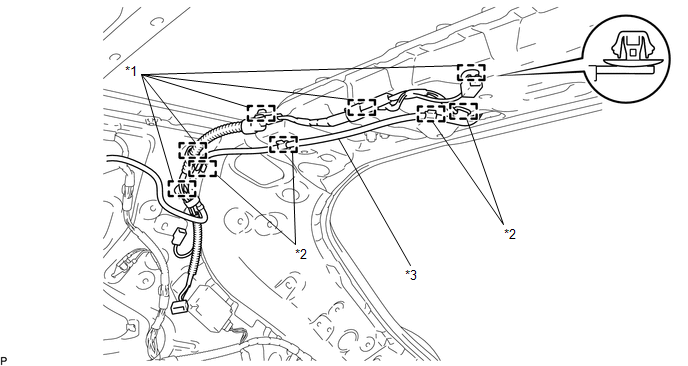
11. REMOVE NO. 3 ANTENNA CORD SUB-ASSEMBLY
(a) w/o Satellite Radio:
|
(1) Disconnect the 2 connectors. |
|
.png)
(2) Disengage the 4 hooks and disconnect the washer hose.
(3) Disengage the 7 clamps.
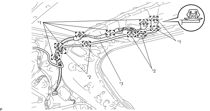 Text in Illustration
|
*1 |
Clamp |
*2 |
Hook |
|
*3 |
Washer Hose |
- |
- |
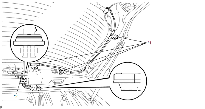
(b) w/ Satellite Radio:
|
(1) Disconnect the connector. |
|
(2) Disengage the 4 hooks and disconnect the washer hose.
(3) Disengage the 5 clamps.
 Text in Illustration
|
*1 |
Clamp |
*2 |
Hook |
|
*3 |
Washer Hose |
- |
- |
|
(c) Disconnect the connector and disengage the clamp. |
|
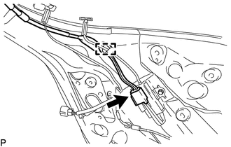
(d) Disengage the 4 clamps.
 Text in Illustration
|
*1 |
Clamp |
*2 |
Grommet |
(e) Disconnect the grommet from the back door.
(f) Disengage the 2 claws.
|
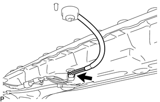
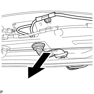
(g) Remove the No. 3 antenna cord sub-assembly with the washer hose as shown in the illustration. |
|
 Components
COMPONENTS
ILLUSTRATION
ILLUSTRATION
ILLUSTRATION
ILLUSTRATION
...
 Installation
INSTALLATION
PROCEDURE
1. INSTALL NO. 3 ANTENNA CORD SUB-ASSEMBLY
(a) Pass the washer hose through the No. 3 antenna cord sub-assembly.
(b) Pass the No. 3 antenna cord sub-assembly with ...
Other materials about Toyota Venza:
Reassembly
REASSEMBLY
CAUTION / NOTICE / HINT
NOTICE:
When using a vise, do not overtighten it.
PROCEDURE
1. INSTALL STEERING LOCK ACTUATOR ASSEMBLY (w/ Smart Key System)
(a) Secure the steering column assembly in a vise.
(b) Temporarily install the ste ...
Installation
INSTALLATION
PROCEDURE
1. INSTALL FRONT SHOULDER BELT ANCHOR ADJUSTER ASSEMBLY
(a) Engage the adjuster positioning hole with the guide and install the
front shoulder belt anchor adjuster assembly with the 2 bolts.
Torque:
42 N·m {428 ...
Removal
REMOVAL
CAUTION / NOTICE / HINT
HINT:
Use the same procedure for the RH side and LH side.
The following procedure is for the LH side.
The rear speed sensor is a component of the rear axle hub and bearing
assembly. If the sensor malfuncti ...

0.1306