Toyota Venza: Installation
INSTALLATION
PROCEDURE
1. INSTALL SEPARATE TYPE FRONT SEAT CUSHION COVER
|
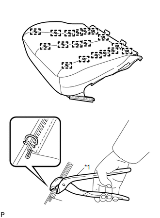
(a) Using a tacker, install the separate type front seat cushion heater to the end of the separate type front seat cushion cover with 25 new tack pins. NOTICE: Be careful not to damage the cushion. |
|
.png)
|
(b) Using hog ring pliers, temporarily install the separate type front seat cover with 18 new hog rings. Text in Illustration
NOTICE:
|
|
2. INSTALL SEPARATE TYPE FRONT SEAT CUSHION COVER WITH PAD
.gif)
3. INSTALL POWER SEAT SWITCH
4. INSTALL FRONT INNER SEAT CUSHION SHIELD
5. INSTALL FRONT SEAT INNER BELT ASSEMBLY
6. INSTALL FRONT SEAT CUSHION SHIELD ASSEMBLY
7. INSTALL SLIDE AND VERTICAL POWER SEAT SWITCH KNOB
8. INSTALL RECLINING POWER SEAT SWITCH KNOB
9. INSTALL FRONT SEAT ASSEMBLY
10. INSTALL FRONT SEAT REAR INNER TRACK COVER
11. INSTALL FRONT SEAT REAR OUTER TRACK COVER
12. INSTALL FRONT SEAT HEADREST ASSEMBLY
13. INSPECT FRONT SEAT ASSEMBLY
14. INSPECT SRS WARNING LIGHT
(See page )
 Inspection
INSPECTION
PROCEDURE
1. INSPECT FRONT SEAT CUSHION HEATER LH
(a) Check the seat cushion heater.
(1) Apply battery voltage and check the seat cushion heater.
OK:
...

Other materials about Toyota Venza:
Luggage compartment light
1. Door position
2. Off
- Adjusting the rear personal/interior lights angle
Push the edge of the light lens.
- To prevent the battery from being discharged
►Vehicles with smart key system
If the personal/interior lights and “ENGIN ...
Speed Sensor(when Not Using The Engine Support Bridge)
Components
COMPONENTS
ILLUSTRATION
Removal
REMOVAL
PROCEDURE
1. REMOVE AUTOMATIC TRANSAXLE ASSEMBLY
HINT:
See the steps from "Remove Engine Assembly with transaxle" through "Remove Automatic
Transaxle Assembly" (See page ). ...
Turn Signal Flasher Assembly
Components
COMPONENTS
ILLUSTRATION
Inspection
INSPECTION
PROCEDURE
1. INSPECT TURN SIGNAL FLASHER ASSEMBLY
(a) Disconnect the D34 turn signal flasher assembly connector.
(b) Measure the vo ...

0.1761