Toyota Venza: Installation
INSTALLATION
PROCEDURE
1. INSTALL CHECK VALVE GROMMET
(a) Install a new check valve grommet to the brake booster assembly.
2. INSTALL BRAKE VACUUM CHECK VALVE ASSEMBLY
(a) Install the brake vacuum check valve assembly to the brake booster assembly.
3. INSTALL BRAKE MASTER CYLINDER PUSH ROD CLEVIS
(a) Temporarily install the lock nut and brake master cylinder push rod clevis to the brake booster assembly.
|
(b) Set the push rod length as shown in the illustration. Text in Illustration
Standard length*1: 155.1 to 156.1 mm (6.11 to 6.15 in.) |
|
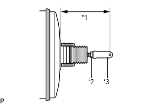
(c) Tighten the lock nut.
Torque:
26 N·m {265 kgf·cm, 19 ft·lbf}
4. INSTALL BRAKE BOOSTER GASKET
|
(a) Install a new brake booster gasket to the brake booster assembly. |
|
.png)
5. INSTALL BRAKE BOOSTER ASSEMBLY
|
(a) Install the brake booster assembly to the body with the 4 nuts. Torque: 13 N·m {130 kgf·cm, 9 ft·lbf} NOTICE: Do not damage the brake lines. |
|
.png)
6. INSTALL PUSH ROD PIN
|
(a) Apply lithium soap base glycol grease to the push rod pin. |
|
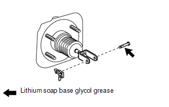
(b) Connect the brake master cylinder push rod clevis to the brake pedal sub-assembly, and install the push rod pin and a new clip as shown in the illustration.
7. INSTALL NO. 1 VACUUM HOSE CONNECTOR (for 1AR-FE)
|
(a) Install the No. 1 vacuum hose connector with the 2 nuts. Torque: 5.4 N·m {55 kgf·cm, 48 in·lbf} |
|
.png)
(b) Connect the vacuum hose to the brake booster assembly, and slide the clip to secure the vacuum hose.
8. CONNECT VACUUM HOSE (for 2GR-FE)
|
(a) Connect the vacuum hose to the brake booster assembly, and slide the clip to secure the vacuum hose. |
|
.png)
9. INSTALL BRAKE MASTER CYLINDER SUB-ASSEMBLY
.gif)
10. FILL RESERVOIR WITH BRAKE FLUID
11. BLEED BRAKE MASTER CYLINDER
12. BLEED BRAKE LINE
13. INSPECT FOR BRAKE FLUID LEAK
14. INSPECT FLUID LEVEL IN RESERVOIR
15. INSPECT AND ADJUST BRAKE PEDAL
HINT:
See page
16. INSTALL SECURITY HORN ASSEMBLY (w/ Security Horn)
17. INSTALL AIR CLEANER CASE (for 1AR-FE)
18. INSTALL AIR CLEANER CASE (for 2GR-FE)
19. INSTALL AIR CLEANER FILTER ELEMENT SUB-ASSEMBLY
20. INSTALL AIR CLEANER CAP SUB-ASSEMBLY (for 1AR-FE)
21. INSTALL AIR CLEANER CAP SUB-ASSEMBLY (for 2GR-FE)
22. INSTALL OUTER COWL TOP PANEL
23. INSTALL WINDSHIELD WIPER MOTOR AND LINK ASSEMBLY
24. INSTALL COWL TOP VENTILATOR LOUVER SUB-ASSEMBLY
25. INSTALL FRONT FENDER TO COWL SIDE SEAL RH
26. INSTALL FRONT FENDER TO COWL SIDE SEAL LH
27. INSTALL FRONT WIPER ARM AND BLADE ASSEMBLY RH
28. INSTALL FRONT WIPER ARM AND BLADE ASSEMBLY LH
29. INSTALL FRONT WIPER ARM HEAD CAP
 Inspection
INSPECTION
PROCEDURE
1. INSPECT BRAKE VACUUM CHECK VALVE ASSEMBLY
(a) Check that there is ventilation from the booster to the engine, and
no ventilation from the engine to the booste ...
 Brake Fluid
...
Other materials about Toyota Venza:
Installation
INSTALLATION
PROCEDURE
1. INSTALL FRONT POWER SEAT LUMBAR SWITCH
(a) Install the front power seat lumbar switch with the 2 screws.
2. INSTALL FRONT SEAT CUSHION SHIELD ASSEMBLY
3. INSTALL SLIDE ...
On-vehicle Inspection
ON-VEHICLE INSPECTION
PROCEDURE
1. INSPECT COOLER CONDENSER ASSEMBLY
(a) If the cooler condenser assembly fins are dirty, clean them with water and
dry with compressed air.
NOTICE:
Do not damage the cooler condenser assembly fins.
(b) If any cooler con ...
Radio Antenna Pole
Components
COMPONENTS
ILLUSTRATION
Removal
REMOVAL
PROCEDURE
1. REMOVE ROOF ANTENNA POLE SUB-ASSEMBLY
(a) Turn the roof antenna pole sub-assembly in the direction indicated
by the arrow in the illustration to remove it.
...

0.1407