Toyota Venza: Inspection
INSPECTION
PROCEDURE
1. INSPECT FRONT SEAT CUSHION HEATER LH
|
(a) Check the seat cushion heater. (1) Apply battery voltage and check the seat cushion heater. OK:
If the result is not as specified, replace the seat cushion heater. NOTICE: Immediately after confirming that the seat heater is functioning normally, remove the battery leads. Failing to do so may cause the seat heater to overheat. |
|
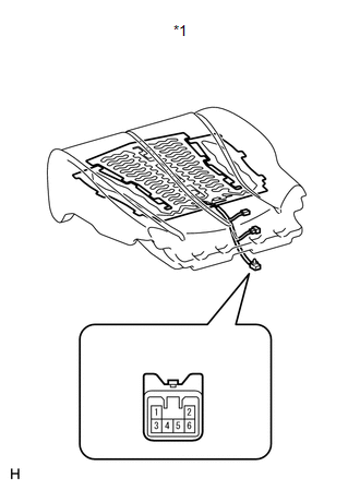
(b) Check the thermostat.
(1) Apply battery voltage and check the seat cushion heater.
OK:
|
Measurement Condition |
Condition |
Specified Condition |
|---|---|---|
|
Battery positive (+) → Terminal 4 Battery negative (-) → Terminal 6 |
Always |
Seat cushion heater temperature below 55°C (129°F) |
If the result is not as specified, replace the seat cushion heater.
NOTICE:
Immediately after confirming that the seat heater is functioning normally, remove the battery leads. Failing to do so may cause the seat heater to overheat.
 Removal
REMOVAL
PROCEDURE
1. REMOVE FRONT SEAT HEADREST ASSEMBLY
2. REMOVE FRONT SEAT REAR OUTER TRACK COVER
3. REMOVE FRONT SEAT REAR INNER TRACK COVER
4. REMOVE FRONT SEAT ASSEMBLY
5. REMOVE ...
 Installation
INSTALLATION
PROCEDURE
1. INSTALL SEPARATE TYPE FRONT SEAT CUSHION COVER
(a) Using a tacker, install the separate type front seat cushion heater
to the end of the separate type front ...
Other materials about Toyota Venza:
Steering wheel
The steering wheel can be adjusted to a comfortable position.
Hold the steering wheel and press the lever down.
Adjust to the ideal position by moving the steering wheel horizontally and vertically.
After adjustment, pull the lever up to secure the stee ...
Power back door switch (vehicles with power back door)
Push the switch to close.
Pressing the switch again while the power back door is closing will cause it
to open again.
However, the reverse operation cannot be performed for the first second after
pressing the switch to close the door.
The back door ca ...
Inspection
INSPECTION
CAUTION / NOTICE / HINT
HINT:
Use the same procedure for the intake side and exhaust side.
PROCEDURE
1. INSPECT CAMSHAFT TIMING OIL CONTROL VALVE ASSEMBLY
(a) Measure the resistance according to the value(s) in the table below.
S ...

0.1316