Toyota Venza: Door Mirror Foot Light Circuit
DESCRIPTION
The main body ECU (driver side junction block assembly) controls the door mirror foot lights.
WIRING DIAGRAM
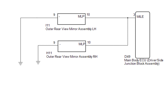
1. w/o Seat Position Memory:
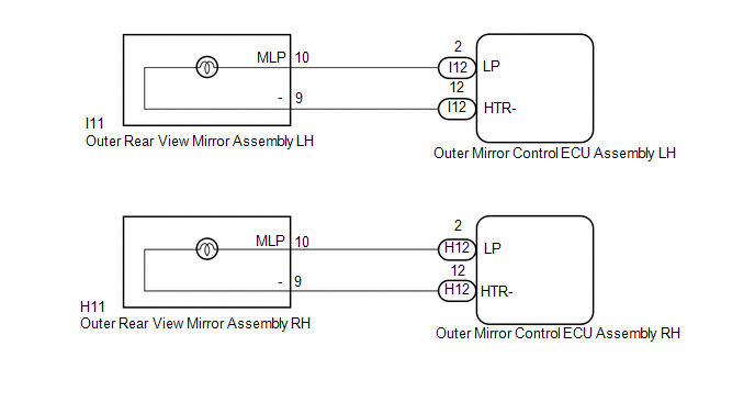
2. w/ Seat Position Memory:
PROCEDURE
|
1. |
CHECK VEHICLE CONDITION |
(a) Check the vehicle condition.
|
Result |
Proceed to |
|---|---|
|
w/o Seat Position Memory |
A |
|
w/ Seat Position Memory |
B |
| B | .gif) |
GO TO STEP 5 |
|
.gif)
|
2. |
PERFORM ACTIVE TEST USING TECHSTREAM |
(a) Connect the Techstream to the DLC3.
(b) Turn the ignition switch to ON.
(c) Turn the Techstream on.
(d) Enter the following menus: Body Electrical / Main Body / Active Test.
(e) Check that the door mirror foot lights operate.
Main Body|
Tester Display |
Test Part |
Control Range |
Diagnostic Note |
|---|---|---|---|
|
Side Mirror Foot Light |
Door mirror foot lights |
ON/OFF |
- |
OK:
Door mirror foot lights illuminate.
| OK | |
PROCEED TO NEXT SUSPECTED AREA SHOWN IN PROBLEM SYMPTOMS TABLE |
|
|
3. |
INSPECT OUTER REAR VIEW MIRROR ASSEMBLY |
|
(a) Remove the outer rear view mirror assembly that does not illuminate
(See page |
|
.gif) ).
).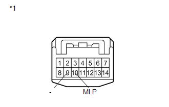
(b) Connect a positive (+) lead from the battery to terminal 10 (MLP) and a negative (-) lead to terminal 9 (-).
(c) Check that the outer mirror foot light comes on.
|
Result |
Proceed to |
|---|---|
|
OK |
A |
|
NG (Door mirror foot light LH does not come on) |
B |
|
NG (Door mirror foot light RH does not come on) |
C |
|
*1 |
Component without harness connected (Outer Rear View Mirror Assembly LH) (Outer Rear View Mirror Assembly RH) |
| B | |
REPLACE OUTER REAR VIEW MIRROR ASSEMBLY LH |
| C | |
REPLACE OUTER REAR VIEW MIRROR ASSEMBLY RH |
|
|
4. |
CHECK HARNESS AND CONNECTOR (MAIN BODY ECU - OUTER REAR VIEW MIRROR ASSEMBLY) |
(a) Disconnect the D49 main body ECU (driver side junction block assembly) connector.
(b) Disconnect the I11 or H11 outer rear view mirror assembly connector.
(c) Measure the resistance according to the value(s) in the table below.
Standard Resistance:
|
Tester Connection |
Condition |
Specified Condition |
|---|---|---|
|
I11-10 (MLP) - D49-3 (MILE) |
Always |
Below 1 Ω |
|
H11-10 (MLP) - D49-3 (MILE) |
Always |
Below 1 Ω |
|
D49-3 (MILE) - Body ground |
Always |
10 kΩ or higher |
| OK | |
REPLACE MAIN BODY ECU (DRIVER SIDE JUNCTION BLOCK ASSEMBLY) |
| NG | |
REPAIR OR REPLACE HARNESS OR CONNECTOR |
|
5. |
PERFORM ACTIVE TEST USING TECHSTREAM |
(a) Connect the Techstream on the DLC3.
(b) Turn the ignition switch to ON.
(c) Turn the Techstream on.
(d) Enter the following menus: Body Electrical / Mirror L or Mirror R / Active Test.
(e) Check that the door mirror foot lights operate.
Mirror L|
Tester Display |
Test Part |
Control Range |
Diagnostic Note |
|---|---|---|---|
|
Foot Light |
Door mirror foot light LH |
ON/OFF |
- |
|
Tester Display |
Test Part |
Control Range |
Diagnostic Note |
|---|---|---|---|
|
Foot Light |
Door mirror foot light RH |
ON/OFF |
- |
|
Result |
Proceed to |
|---|---|
|
OK |
A |
|
NG (Door mirror foot light LH does not come on) |
B |
|
NG (Door mirror foot light RH does not come on) |
C |
| A | |
PROCEED TO NEXT SUSPECTED AREA SHOWN IN PROBLEM SYMPTOMS TABLE |
| C | |
GO TO STEP 8 |
|
|
6. |
INSPECT OUTER REAR VIEW MIRROR ASSEMBLY LH |
|
(a) Remove the outer rear view mirror assembly LH (See page
|
|
(b) Connect a positive (+) lead from the battery to terminal 10 (MLP) and a negative (-) lead to terminal 9 (-).
(c) Check that the outer mirror foot light comes on.
OK:
Door mirror foot light comes on.
Text in Illustration|
*1 |
Component without harness connected (Outer Rear View Mirror Assembly LH) |
| NG | |
REPLACE OUTER REAR VIEW MIRROR ASSEMBLY LH |
|
|
7. |
CHECK HARNESS AND CONNECTOR (OUTER MIRROR CONTROL ECU ASSEMBLY LH - OUTER REAR VIEW MIRROR ASSEMBLY LH) |
(a) Disconnect the I12 outer mirror control ECU assembly LH connector.
(b) Measure the resistance according to the value(s) in the table below.
Standard Resistance:
|
Tester Connection |
Condition |
Specified Condition |
|---|---|---|
|
I12-2 (LP) - I11-10 (MLP) |
Always |
Below 1 Ω |
|
I12-2 (LP) - Body ground |
Always |
10 kΩ or higher |
|
I12-12 (HTR-) - I11-9 (-) |
Always |
Below 1 Ω |
|
I12-12 (HTR-) - Body ground |
Always |
10 kΩ or higher |
| OK | |
REPLACE OUTER MIRROR CONTROL ECU ASSEMBLY LH |
| NG | |
REPAIR OR REPLACE HARNESS OR CONNECTOR |
|
8. |
INSPECT OUTER REAR VIEW MIRROR ASSEMBLY RH |
|
(a) Remove the outer rear view mirror assembly RH (See page
|
|
(b) Connect a positive (+) lead from the battery to terminal 10 (MLP) and a negative (-) lead to terminal 9 (-).
(c) Check that the outer mirror foot light comes on.
OK:
Door mirror foot light comes on.
Text in Illustration|
*1 |
Component without harness connected (Outer Rear View Mirror Assembly RH) |
| NG | |
REPLACE OUTER REAR VIEW MIRROR ASSEMBLY RH |
|
|
9. |
CHECK HARNESS AND CONNECTOR (OUTER MIRROR CONTROL ECU ASSEMBLY RH - OUTER REAR VIEW MIRROR ASSEMBLY RH) |
(a) Disconnect the H12 outer mirror control ECU assembly RH connector.
(b) Measure the resistance according to the value(s) in the table below.
Standard Resistance:
|
Tester Connection |
Condition |
Specified Condition |
|---|---|---|
|
H12-2 (LP) - H11-10 (MLP) |
Always |
Below 1 Ω |
|
H12-2 (LP) - Body ground |
Always |
10 kΩ or higher |
|
H12-12 (HTR-) - H11-9 (-) |
Always |
Below 1 Ω |
|
H12-12 (HTR-) - Body ground |
Always |
10 kΩ or higher |
| OK | |
REPLACE OUTER MIRROR CONTROL ECU ASSEMBLY RH |
| NG | |
REPAIR OR REPLACE HARNESS OR CONNECTOR |
 Light Control Switch Circuit
DESCRIPTION
The main body ECU (driver side junction block assembly) receives the following
switch information:
Light control switch position off, tail, head or AUTO
Dimmer switch positi ...
 Parking Brake Switch Circuit
DESCRIPTION
The main body ECU (driver side junction block assembly) detects the condition
of the parking brake switch.
WIRING DIAGRAM
PROCEDURE
1.
READ VALUE USING TECHS ...
Other materials about Toyota Venza:
Noise Occurs
PROCEDURE
1.
CHECK NOISE CONDITION
(a) Check from which direction the noise comes (front left or right, or rear
left or right).
OK:
The location of the noise source can be determined.
NG
GO TO STEP 3
...
Turn signal lever
1. Right turn
2. Left turn
3. Move and hold the lever partway to signal a lane change.
The right hand signal will flash until you release the lever.
4. Move and hold the lever partway to signal a lane change.
The left hand signal will flash until you re ...
Installation
INSTALLATION
PROCEDURE
1. INSTALL PARK/NEUTRAL POSITION SWITCH ASSEMBLY
(a) Move the shift lever to N.
(b) Align the protrusions of the park/neutral position switch.
Text in Illustration
*1
Protrusion
...

0.1326