Toyota Venza: Installation
INSTALLATION
PROCEDURE
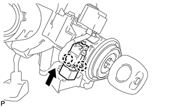
1. INSTALL UNLOCK WARNING SWITCH
|
(a) Engage the 2 claws and install the unlock warning switch to the steering column upper bracket. |
|
(b) Extract the key.
|
(c) Connect the connector. |
|
.png)
2. INSTALL TURN SIGNAL SWITCH ASSEMBLY WITH SPIRAL CABLE SUB-ASSEMBLY
.gif)
3. INSTALL UPPER STEERING COLUMN COVER
4. INSTALL LOWER STEERING COLUMN COVER
5. ALIGN FRONT WHEELS FACING STRAIGHT AHEAD
6. ADJUST SPIRAL CABLE
7. INSTALL STEERING WHEEL ASSEMBLY
8. INSTALL STEERING PAD
9. INSTALL LOWER NO. 3 STEERING WHEEL COVER
10. INSTALL LOWER NO. 2 STEERING WHEEL COVER
11. INSPECT STEERING WHEEL CENTER POINT
12. CONNECT CABLE TO NEGATIVE BATTERY TERMINAL
NOTICE:
When disconnecting the cable, some systems need to be initialized after the cable
is reconnected (See page ).
13. INSPECT STEERING PAD
14. INSPECT SRS WARNING LIGHT
(See page )
 Removal
REMOVAL
PROCEDURE
1. ALIGN FRONT WHEELS FACING STRAIGHT AHEAD
2. DISCONNECT CABLE FROM NEGATIVE BATTERY TERMINAL
CAUTION:
Wait at least 90 seconds after disconnecting the cable from the negative ...
 Wireless Door Lock Buzzer
Components
COMPONENTS
ILLUSTRATION
Installation
INSTALLATION
PROCEDURE
1. INSTALL WIRELESS DOOR LOCK BUZZER
(a) Engage the clamp and install the wireless door lock buzzer.
...
Other materials about Toyota Venza:
Problem Symptoms Table
PROBLEM SYMPTOMS TABLE
HINT:
Use the table below to help determine the cause of problem symptoms.
If multiple suspected areas are listed, the potential causes of the symptoms
are listed in order of probability in the "Suspected Area" ...
XM Tuner Malfunction (B15BA)
DESCRIPTION
These DTCs are stored when a malfunction occurs in the stereo component tuner
assembly.
DTC No.
DTC Detection Condition
Trouble Area
B15BA
When either of the following conditions is m ...
Unlocking and locking the doors
►Front door handle
Grip the driver’s door handle to unlock the door. Grip the passenger’s door handle
to unlock all the doors.* Make sure to touch the sensor on the back of the handle.
The doors cannot be unlocked for 3 seconds after the doors ...

0.1229