Toyota Venza: Wireless Door Lock Buzzer
Components
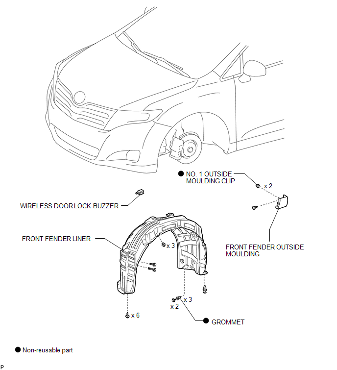
COMPONENTS
ILLUSTRATION
Installation
INSTALLATION
PROCEDURE
1. INSTALL WIRELESS DOOR LOCK BUZZER
|
(a) Engage the clamp and install the wireless door lock buzzer. |
|
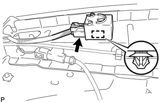
(b) Connect the connector.
2. INSTALL FRONT FENDER LINER
.gif)
3. INSTALL FRONT FENDER OUTSIDE MOULDING
4. INSTALL FRONT WHEEL
Removal
REMOVAL
PROCEDURE
1. REMOVE FRONT WHEEL
2. REMOVE FRONT FENDER OUTSIDE MOULDING
.gif)
3. REMOVE FRONT FENDER LINER
4. REMOVE WIRELESS DOOR LOCK BUZZER
|
(a) Disconnect the connector. |
|
.png)
(b) Disengage the clamp and remove the wireless door lock buzzer.
 Installation
INSTALLATION
PROCEDURE
1. INSTALL UNLOCK WARNING SWITCH
(a) Engage the 2 claws and install the unlock warning switch to the steering
column upper bracket.
...

Other materials about Toyota Venza:
System Diagram
SYSTEM DIAGRAM
Communication Table
Transmitting ECU
Receiving ECU
Signal
Communication Method
Air Conditioning Control Assembly
Air Conditioning Amplifier Assembly
Rear windo ...
Freeze Frame Data
FREEZE FRAME DATA
1. FREEZE FRAME DATA
(a) Whenever an ABS DTC is detected, the skid control ECU stores the current
vehicle (sensor) state as Freeze Frame Data.
(b) The skid control ECU stores the number of times (maximum: 31) the ignition
switch has be ...
No Sound can be Heard from Speakers
PROCEDURE
1.
CHECK AUDIO SETTINGS
(a) In sound output setting mode, set volume, fader and balance to the initial
values and check that the sound is normal.
OK:
Audio system returns to normal.
HINT:
Sound quality adjustm ...

0.1547