Toyota Venza: On-vehicle Inspection
ON-VEHICLE INSPECTION
PROCEDURE
1. INSPECT REAR COMBINATION LIGHT ASSEMBLY
|
(a) Disconnect the connector from the rear combination light assembly. |
|
(b) Measure the voltage according to the value(s) in the table below.
Standard Voltage:
LH Side|
Tester Connection |
Condition |
Specified Condition |
|---|---|---|
|
L16-1 - L16-3 |
Light control switch off |
Below 1 V |
|
Light control switch in tail position |
11 to 14 V |
|
|
L16-2 - L16-3 |
Brake pedal released |
Below 1 V |
|
Brake pedal depressed |
11 to 14 V |
|
|
L16-4 - L16-3 |
Turn signal switch in neutral position |
Below 1 V |
|
Ignition switch ON and turn signal switch in left turn position |
11 to 14 V (60 to 120 times per minute) |
|
Tester Connection |
Condition |
Specified Condition |
|---|---|---|
|
M11-1 - M11-3 |
Light control switch off |
Below 1 V |
|
Light control switch in tail position |
11 to 14 V |
|
|
M11-2 - M11-3 |
Brake pedal released |
Below 1 V |
|
Brake pedal depressed |
11 to 14 V |
|
|
M11-4 - M11-3 |
Turn signal switch neutral position |
Below 1 V |
|
Ignition switch ON and turn signal switch in right turn position |
11 to 14 V (60 to 120 times per minute) |
|
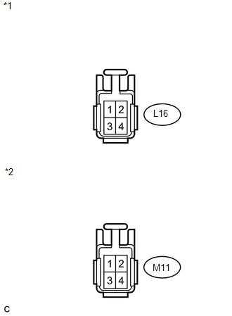
*1 |
Front view of wire harness connector (to Rear Combination Light Assembly LH) |
|
*2 |
Front view of wire harness connector (to Rear Combination Light Assembly RH) |
If the result is not as specified, repair or replace the wire harness or connector.
 Components
COMPONENTS
ILLUSTRATION
ILLUSTRATION
ILLUSTRATION
ILLUSTRATION
ILLUSTRATION
ILLUSTRATION
ILLUSTRATION
...
 Removal
REMOVAL
PROCEDURE
1. REMOVE REAR DOOR SCUFF PLATE
2. DISCONNECT REAR DOOR OPENING TRIM WEATHERSTRIP
3. REMOVE TONNEAU COVER ASSEMBLY (w/ Tonneau Cover)
4. REMOVE DECK BOARD ASSEMBLY
...
Other materials about Toyota Venza:
How To Proceed With Troubleshooting
CAUTION / NOTICE / HINT
HINT:
Use the following procedure to troubleshoot.
PROCEDURE
1.
VEHICLE BROUGHT TO WORKSHOP
NEXT
2.
CUSTOMER PR ...
Speed Sensor(when Not Using The Engine Support Bridge)
Components
COMPONENTS
ILLUSTRATION
Removal
REMOVAL
PROCEDURE
1. REMOVE AUTOMATIC TRANSAXLE ASSEMBLY
HINT:
See the steps from "Remove Engine Assembly with transaxle" through "Remove Automatic
Transaxle Assembly" (See page ). ...
System Diagram
SYSTEM DIAGRAM
1. MIRROR CONTROL SYSTEM
Communication Table
Sender
Receiver
Signal / Signal Condition
Line
Main body ECU (driver side junction block assembly)
Outer mirror control EC ...

0.119