Toyota Venza: Installation
INSTALLATION
PROCEDURE
1. INSTALL DISCHARGE HEADLIGHT BULB
HINT:
Use the same procedure for the RH side and LH side (See page
.gif) ).
).
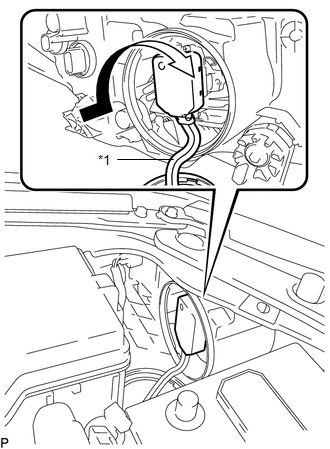
2. INSTALL LIGHT CONTROL ECU (for LH Side)
|
(a) Turn the socket of the light control ECU in the direction indicated by the arrow shown in the illustration to connect it. Text in Illustration
NOTICE:
|
|
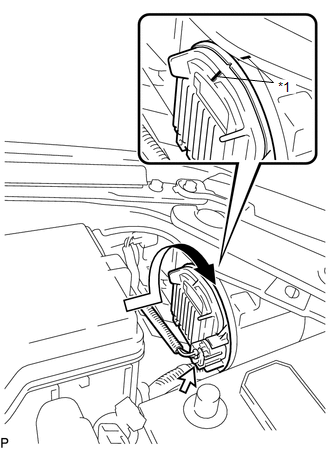
(b) Check that the red line on the output harness is not twisted and store the harness in the headlight assembly securely so that the output harness is not pinched.
|
(c) Turn the light control ECU in the direction indicated by the arrow shown in the illustration until the lock marks are aligned to install it. Text in Illustration
NOTICE:
|
|
(d) Connect the connector.
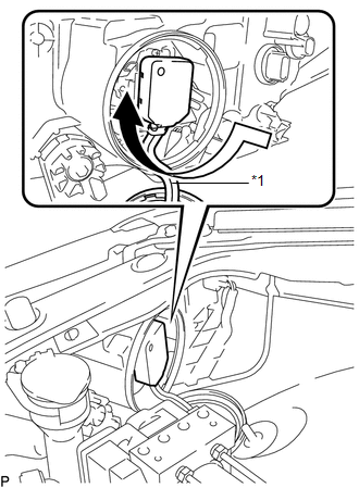
3. INSTALL LIGHT CONTROL ECU (for RH Side)
|
(a) Turn the socket of the light control ECU in the direction indicated by the arrow shown in the illustration to connect it. Text in Illustration
NOTICE:
|
|
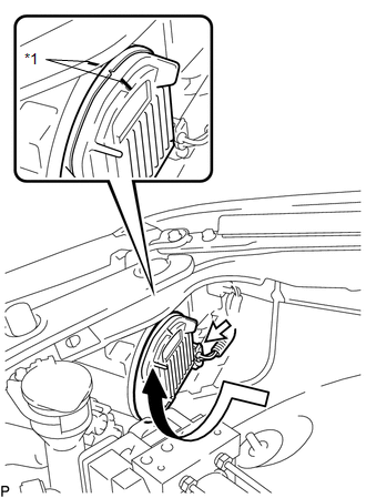
(b) Check that the red line on the output harness is not twisted and store the harness in the headlight assembly securely so that the output harness is not pinched.
|
(c) Turn the light control ECU in the direction indicated by the arrow shown in the illustration until the lock marks are aligned to install it. Text in Illustration
NOTICE:
|
|
(d) Connect the connector.
4. INSTALL RADIATOR RESERVE TANK ASSEMBLY (for RH Side)
5. CONNECT CABLE TO NEGATIVE BATTERY TERMINAL
NOTICE:
When disconnecting the cable, some systems need to be initialized after the cable
is reconnected (See page ).
 On-vehicle Inspection
ON-VEHICLE INSPECTION
PROCEDURE
1. INSPECT DISCHARGE HEADLIGHT BULB
NOTICE:
Confirm the following items before replacing a discharge headlight bulb. If a
malfunction is discovered and repaired, ...
 Removal
REMOVAL
CAUTION / NOTICE / HINT
PROCEDURE
1. PRECAUTION
NOTICE:
After turning the ignition switch off, waiting time may be required before disconnecting
the cable from the negative (-) battery ...
Other materials about Toyota Venza:
Power Source Mode does not Change to ON (ACC)
DESCRIPTION
When the engine switch is pushed with the electrical key in the cabin, the power
management control ECU receives signals to change the power source mode.
HINT:
To allow use of the Techstream to inspect the push-button start function when
the ...
Front Seat Inner Belt Assembly
Components
COMPONENTS
ILLUSTRATION
ILLUSTRATION
Inspection
INSPECTION
PROCEDURE
1. INSPECT FRONT SEAT INNER BELT ASSEMBLY LH (w/ Seat Position Memory System)
(a) Measure the resistance according to the value(s) in the table below.
...
Internal Control Module Throttle Position Performance (P060E)
MONITOR DESCRIPTION
The ECM monitors the input signals of the throttle position sensor No. 1 and
stop light switch. As the ECM monitors the input signals of the throttle position
sensor No. 1 and the STP signals of the stop light switch, if the input sign ...

0.1542