Toyota Venza: Unlock Warning Switch Circuit
DESCRIPTION
The key unlock warning switch assembly turns on when the ignition key is inserted into the ignition key cylinder and turns off when the ignition key is removed.
The main body ECU (driver side junction block assembly) operates the key confinement prevention function while the key unlock warning switch assembly is on.
WIRING DIAGRAM
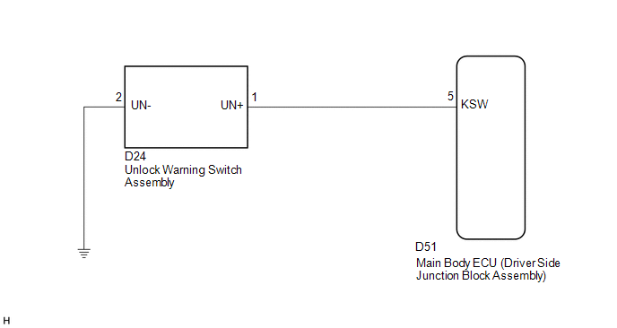
PROCEDURE
|
1. |
READ VALUE USING TECHSTREAM (UNLOCK WARNING SWITCH ASSEMBLY) |
(a) Connect the Techstream to the DLC3.
(b) Turn the ignition switch to ON.
(c) Turn the Techstream on.
(d) Select the item below in the Data List and then read the display on the Techstream.
Main Body|
Tester Display |
Measurement Item/Range |
Normal Condition |
Diagnostic Note |
|---|---|---|---|
|
Key Unlock Warning SW |
Unlock warning switch signal/ON or OFF |
ON: Key inserted into ignition key cylinder OFF: Key removed from ignition key cylinder |
- |
OK:
When the key is in the ignition key cylinder, ON appears on the Techstream.
| OK | .gif) |
PROCEED TO NEXT SUSPECTED AREA SHOWN IN PROBLEM SYMPTOMS TABLE |
|
.gif)
|
2. |
INSPECT UNLOCK WARNING SWITCH ASSEMBLY |
|
(a) Remove the unlock warning switch assembly (See page
|
|
.gif) ).
).
(b) Measure the resistance according to the value(s) in the table below.
Standard Resistance:
|
Tester Connection |
Condition |
Specified Condition |
|---|---|---|
|
D24-1 (UN+) - D24-2 (UN-) |
Free (Key removed) |
10 kΩ or higher |
|
D24-1 (UN+) - D24-2 (UN-) |
Pushed (Key set) |
Below 1 Ω |
|
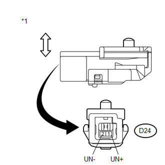
*1 |
Component without harness connected (Unlock Warning Switch Assembly) |
| NG | |
REPLACE UNLOCK WARNING SWITCH ASSEMBLY |
|
|
3. |
CHECK HARNESS AND CONNECTOR (UNLOCK WARNING SWITCH ASSEMBLY - BODY GROUND) |
|
(a) Disconnect the D24 unlock warning switch assembly connector. |
|
(b) Measure the resistance according to the value(s) in the table below.
Standard Resistance:
|
Tester Connection |
Condition |
Specified Condition |
|---|---|---|
|
D24-2 (UN-) - Body ground |
Always |
Below 1 Ω |
|
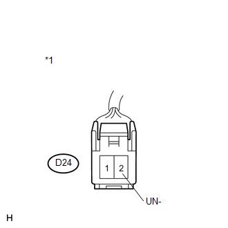
*1 |
Front view of wire harness connector (to Unlock Warning Switch Assembly) |
| NG | |
REPAIR OR REPLACE HARNESS OR CONNECTOR |
|
|
4. |
CHECK HARNESS AND CONNECTOR (UNLOCK WARNING SWITCH ASSEMBLY - MAIN BODY ECU) |
|
(a) Disconnect the D51 main body ECU (driver side junction block assembly) connector. |
|
(b) Measure the resistance according to the value(s) in the table below.
Standard Resistance:
|
Tester Connection |
Condition |
Specified Condition |
|---|---|---|
|
D24-1 (UN+) - D51-5 (KSW) |
Always |
Below 1 Ω |
|
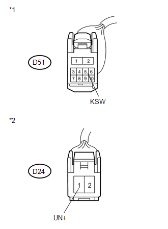
*1 |
Front view of wire harness connector (to Main Body ECU (Driver Side Junction Block Assembly)) |
|
*2 |
Front view of wire harness connector (to Unlock Warning Switch Assembly) |
| OK | |
REPLACE MAIN BODY ECU (DRIVER SIDE JUNCTION BLOCK ASSEMBLY) |
| NG | |
REPAIR OR REPLACE HARNESS OR CONNECTOR |
 ECU Power Source Circuit
DESCRIPTION
This circuit provides power for main body ECU (driver side junction block assembly)
operation.
WIRING DIAGRAM
PROCEDURE
1.
CHECK DRIVER SIDE JUNCTION BLOCK A ...
 Transponder Key Amplifier
Components
COMPONENTS
ILLUSTRATION
Removal
REMOVAL
PROCEDURE
1. REMOVE FRONT DOOR SCUFF PLATE
2. REMOVE COWL SIDE TRIM SUB-ASSEMBLY
3. REMOVE LOWER NO. 1 INSTRUMENT PANEL FINISH PA ...
Other materials about Toyota Venza:
Installation
INSTALLATION
PROCEDURE
1. INSTALL FRONT DOOR FRONT WINDOW FRAME MOULDING
(a) Engage the front door front window frame moulding to the door frame.
(b) Using an air riveter or hand riveter with a nose ...
Removal
REMOVAL
CAUTION / NOTICE / HINT
HINT:
Use the same procedure for the RH side and LH side.
The procedure listed below is for the LH side.
PROCEDURE
1. DISCONNECT CABLE FROM NEGATIVE BATTERY TERMINAL
CAUTION:
Wait at least 90 seconds aft ...
VC Output Circuit
DESCRIPTION
The ECM constantly generates 5 V of power from battery voltage supplied to the
+B (BATT) terminal to operate the microprocessor. The ECM also provides this power
to the sensors through the VC output circuit.
When the VC circuit is short-cir ...

0.1722