Toyota Venza: Jam Protection Function Activates During Power Back Door Operation
DESCRIPTION
When the jam protection function activates during power back door operation, one of the following may be the cause: 1) improper fit of back door, or a foreign object is stuck in the back door, 2) malfunctioning power back door touch sensor circuit or 3) malfunctioning power back door ECU (power back door motor unit).
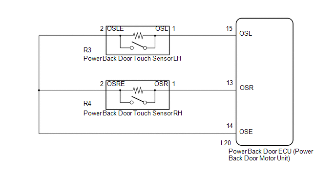
WIRING DIAGRAM
PROCEDURE
|
1. |
CHECK BACK DOOR LOCK FUNCTION |
(a) Check if there are any foreign objects interfering with back door operation.
OK:
There are no foreign objects.
| NG | .gif) |
REMOVE FOREIGN OBJECT |
|
.gif)
|
2. |
CHECK BACK DOOR |
(a) Check back door operation.
(1) Turn the power back door main switch off.
(2) Open/close the back door by hand.
OK:
The back door fully opens and closes smoothly.
| NG | |
ADJUST BACK DOOR |
|
|
3. |
READ VALUE USING TECHSTREAM (POWER BACK DOOR TOUCH SENSOR) |
(a) Connect the Techstream to the DLC3.
(b) Turn the ignition switch to ON.
(c) Turn the Techstream on.
(d) Enter the following menus: Body Electrical / Back Door / Data List.
(e) Check the Data List to determine if the power back door touch sensor functions properly.
Back Door (Power Back Door ECU)|
Tester Display |
Measurement Item/Range |
Normal Condition |
Diagnostic Note |
|---|---|---|---|
|
PBD Touch Sensor (Right) |
Power back door touch sensor RH signal / ON , OFF or Open |
ON: Power back door touch sensor RH pressed OFF: Power back door touch sensor RH not pressed Open: Power back door touch sensor RH circuit open |
- |
|
PBD Touch Sensor (Left) |
Power back door touch sensor LH signal / ON , OFF or Open |
ON: Power back door touch sensor LH pressed OFF: Power back door touch sensor LH not pressed Open: Power back door touch sensor LH circuit open |
- |
|
Result |
Proceed to |
|---|---|
|
On the Techstream screen, ON or OFF will be displayed accordingly. |
A |
|
On the Techstream screen, ON or OFF will not be displayed accordingly or Open is displayed. |
B |
| A | |
REPLACE POWER BACK DOOR ECU (POWER BACK DOOR MOTOR UNIT) |
| B | |
GO TO OTHER FLOW CHART (TOUCH SENSOR CIRCUIT) |
 Power Back Door cannot be Closed Using the Power Back Door Closer Switch
DESCRIPTION
When the power back door cannot be closed using the power back door closer switch,
either of the following may be malfunctioning: 1) power back door closer switch
circuit or 2) power ...
 Power Back Door Warning System does not Operate
DESCRIPTION
When the power back door warning system does not operate, one of the following
may be malfunctioning: 1) power back door warning buzzer circuit, 2) wireless door
lock control system o ...
Other materials about Toyota Venza:
Rear Power Window LH Auto Up / Down Function does not Operate with Rear Power
Window Switch LH
DESCRIPTION
If the manual up/down function can be performed but the auto up/down function
cannot, the fail-safe mode may be functioning.
If the power window initialization (See page
) has not been performed, the auto up/down function
will not operate.
...
Precaution
PRECAUTION
1. INITIALIZATION
NOTICE:
Perform the Registration (VIN registration) when replacing the ECM (See page
).
HINT:
Reset memory or initialization cannot be completed by only disconnecting and
reconnecting the cable of the negative (-) battery ...
Power Seat does not Return to Memorized Position
DESCRIPTION
When either the M1 or M2 switch is pressed, the outer mirror control ECU assembly
LH sends a switch signal to the main body ECU (driver side junction block assembly)
via CAN communication. Then, the main body ECU (driver side junction block as ...

0.1469