Toyota Venza: System Diagram
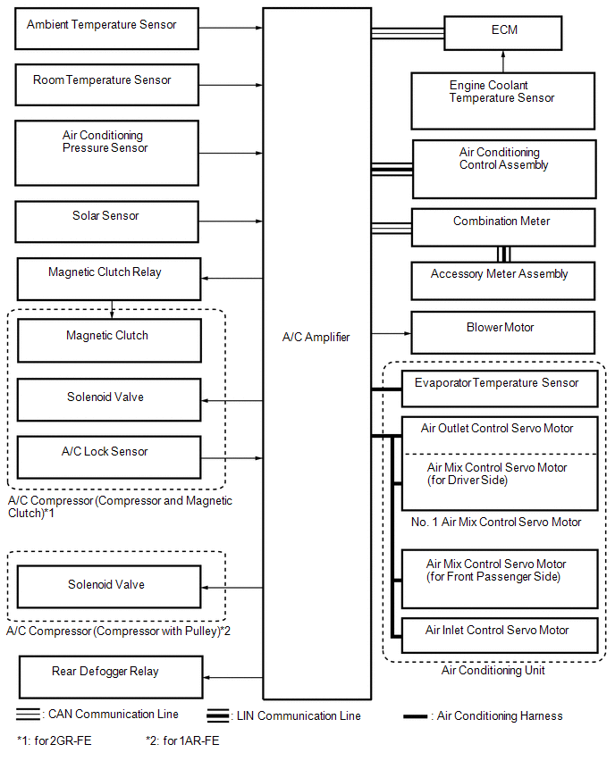
SYSTEM DIAGRAM
 Communication Table
|
Sender |
Receiver |
Signal |
Communication Line |
|---|---|---|---|
|
A/C amplifier |
ECM |
Magnetic clutch request signal*1 |
CAN |
|
Idle up request signal |
|||
|
External variable control solenoid current signal |
|||
|
Cooling fan motor driving request signal |
|||
|
Refrigerant gas pressure sensor signal |
|||
|
Ambient temperature signal |
|||
|
A/C amplifier |
Air conditioning control assembly |
Panel indication signal |
LIN |
|
MODE indication signal |
|||
|
Blower level indication signal |
|||
|
Set temperature indication signal |
|||
|
Combination meter |
A/C amplifier |
Vehicle speed signal |
CAN |
|
ECM |
A/C amplifier |
Engine revolution speed signal |
CAN |
|
Engine coolant temperature signal |
|||
|
A/C control cut signal |
|||
|
Air conditioning control assembly |
A/C amplifier |
AUTO switch signal |
LIN |
|
OFF switch signal |
|||
|
A/C switch signal |
|||
|
Fr DEF switch signal |
|||
|
Rr DEF switch signal |
|||
|
MODE switch signal |
|||
|
REC/FRS switch signal |
|||
|
SYNC switch signal |
|||
|
Blower switch signal (FAN+, FAN-) |
|||
|
Set temperature switch signal (UP, DOWN) |
- *1: for 2GR-FE
 Parts Location
PARTS LOCATION
ILLUSTRATION
ILLUSTRATION
ILLUSTRATION
...
 System Description
SYSTEM DESCRIPTION
1. GENERAL
(a) The air conditioning system has the following controls.
Control
Outline
Neural Network Control
This control is ca ...
Other materials about Toyota Venza:
Check Mode Procedure
CHECK MODE PROCEDURE
1. DESCRIPTION
(a) Check mode has a higher sensitivity to malfunctions and can detect malfunctions
that normal mode cannot detect. Check mode can also detect all the malfunctions
that normal mode can detect. In check mode, DTCs are d ...
Installation
INSTALLATION
PROCEDURE
1. INSTALL NAVIGATION RECEIVER ASSEMBLY
2. INSTALL NO. 2 RADIO RECEIVER BRACKET
(a) Install the No. 2 radio receiver bracket with the 4 screws.
Torque:
5.0 N·m {51 kgf·cm, 44 in·lbf}
3. INSTALL NO. 1 RADIO RECEIVER BRACKET
(a ...
Removal
REMOVAL
PROCEDURE
1. REMOVE REAR BUMPER ASSEMBLY
(See page )
2. REMOVE ULTRASONIC SENSOR CLIP
(a) Disconnect the connector.
Text in Illustration
*A
LH Side
*B
...

0.1139