Toyota Venza: Installation
INSTALLATION
PROCEDURE
1. INSTALL ROOF DRIP SIDE FINISH MOULDING CLIP (w/o Sliding Roof)
NOTICE:
- If reusing the clips, do not remove the double-sided tape remaining on the clips and where the clips will be installed on the body.
- If installing new clips, remove the double-sided tape remaining where the clips will be installed on the body and clean the body with a non-residue solvent.
|
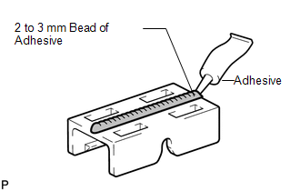
(a) Apply a 2 to 3 mm (0.0787 to 0.118 in.) bead of adhesive (3M DP-105 or equivalent) to new roof drip side finish moulding clips. HINT: Adhesive strength (tensile strength): 13.7 MPa (140 kgf/cm2) or more (when the temperature is 23°C (73°F).) |
|
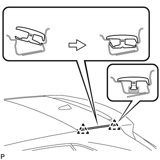
(b) Press and install the 2 roof drip side finish moulding clips.
|
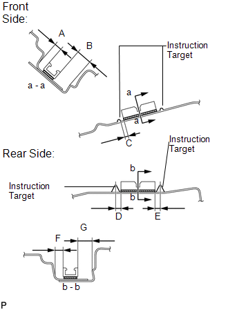
(c) Install the clips to the positions on the roof panel shown in the illustration. Determine the locations and firmly press and install the 2 roof drip side finish moulding clips after lightly applying adhesive (3M DP-105 or equivalent). Standard Dimension
|
|
(d) Install the roof drip center side finish moulding when 20 minutes or more have elapsed after pressing and installing the 2 roof drip side finish moulding clips.
HINT:
- Initial hardening time: 20 minutes
- Complete hardening time: 48 hours
2. INSTALL ROOF DRIP CENTER SIDE FINISH MOULDING (w/o Sliding Roof)
|
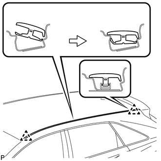
(a) Engage the 2 clips and install the roof drip center side finish moulding as shown in the illustration. |
|
3. INSTALL ROOF DRIP SIDE FINISH MOULDING CLIP (w/ Sliding Roof)
NOTICE:
- If reusing the clips, do not remove the double-sided tape remaining on the clips and where the clips will be installed on the body.
- If installing new clips, remove the double-sided tape remaining where the clips will be installed on the body and clean the body with a non-residue solvent.
|
(a) Apply a 2 to 3 mm (0.0787 to 0.118 in.) bead of adhesive (3M DP-105 or equivalent) to new roof drip side finish moulding clips. HINT: Adhesive strength (tensile strength): 13.7 MPa (140 kgf/cm2) or more (when the temperature is 23°C (73°F).) |
|
(b) Press and install the 2 roof drip side finish moulding clips.
|
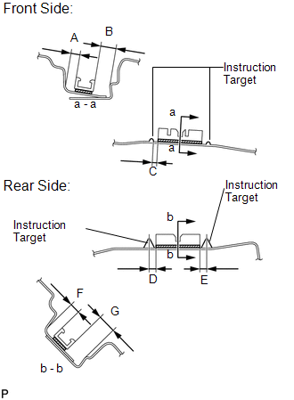
(c) Install the clips to the positions on the roof panel shown in the illustration. Determine the locations and firmly press and install the 2 roof drip side finish moulding clips after lightly applying adhesive (3M DP-105 or equivalent). Standard Dimension
|
|
(d) Install the roof drip center side finish moulding when 20 minutes or more have elapsed after pressing and installing the 2 roof drip side finish moulding clips.
HINT:
- Initial hardening time: 20 minutes
- Complete hardening time: 48 hours
4. INSTALL ROOF DRIP CENTER SIDE FINISH MOULDING (w/ Sliding Roof)
|
(a) Engage the 2 clips and install the roof drip center side finish moulding as shown in the illustration. |
|
 Removal
REMOVAL
PROCEDURE
1. REMOVE ROOF DRIP CENTER SIDE FINISH MOULDING (w/o Sliding Roof)
(a) Put protective tape around the roof drip center side finish moulding.
Text in Illustration
...
 Side Mudguard
...
Other materials about Toyota Venza:
TS and CG Terminal Circuit
DESCRIPTION
In the Test Mode (signal check), a malfunction in the speed sensor that cannot
be detected when the vehicle is stopped can be detected while driving.
Transition to the sensor check mode can be performed by connecting terminals
TS and CG of th ...
Power Back Door cannot be Closed Using the Power Back Door Closer Switch
DESCRIPTION
When the power back door cannot be closed using the power back door closer switch,
either of the following may be malfunctioning: 1) power back door closer switch
circuit or 2) power back door ECU (power back door motor unit).
WIRING DIAGRAM
...
Removal
REMOVAL
CAUTION / NOTICE / HINT
NOTICE:
Do not remove the oil pump or oil pump relief valve from the timing chain cover
sub-assembly.
PROCEDURE
1. INSTALL ENGINE ON ENGINE STAND
(See page )
2. REMOVE IGNITION COIL ASSEMBLY
3. REMOVE CYLINDER HEAD ...

0.1247