Toyota Venza: Center Power Outlet Socket
Components
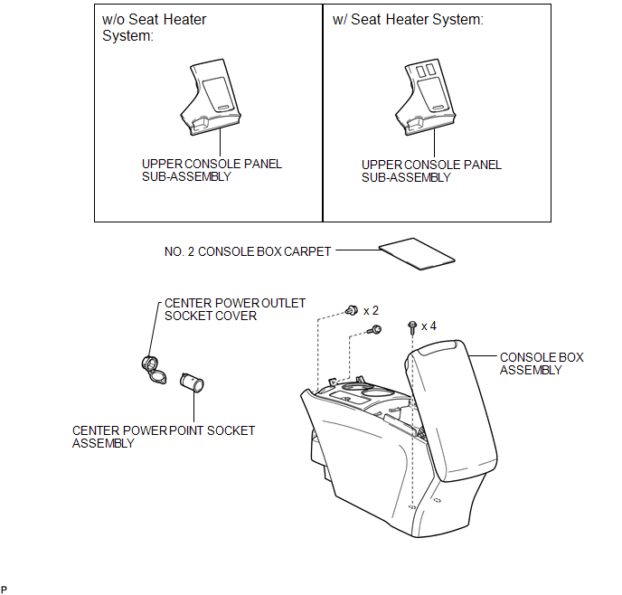
COMPONENTS
ILLUSTRATION
Installation
INSTALLATION
PROCEDURE
1. INSTALL CENTER POWER OUTLET SOCKET COVER
|
(a) Engage the 2 claws to install the center power outlet socket cover. |
|
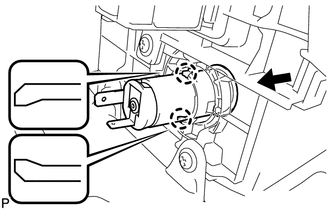
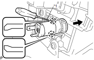
2. INSTALL CENTER POWER POINT SOCKET ASSEMBLY
|
(a) Engage the 2 claws to install the center power point socket assembly as shown in the illustration. |
|
3. INSTALL CONSOLE BOX ASSEMBLY
.gif)
4. INSTALL NO. 2 CONSOLE BOX CARPET
5. INSTALL UPPER CONSOLE PANEL SUB-ASSEMBLY (w/o Seat Heater System)
6. INSTALL UPPER CONSOLE PANEL SUB-ASSEMBLY (w/ Seat Heater System)
Removal
REMOVAL
PROCEDURE
1. REMOVE UPPER CONSOLE PANEL SUB-ASSEMBLY (w/o Seat Heater System)
.gif)
2. REMOVE UPPER CONSOLE PANEL SUB-ASSEMBLY (w/ Seat Heater System)
3. REMOVE NO. 2 CONSOLE BOX CARPET
4. REMOVE CONSOLE BOX ASSEMBLY
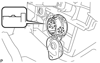
5. REMOVE CENTER POWER POINT SOCKET ASSEMBLY
|
(a) Using a screwdriver, disengage the 2 claws and remove the center power point socket assembly as shown in the illustration. Text in Illustration
HINT: Tape the screwdriver tip before use. |
|
6. REMOVE CENTER POWER OUTLET SOCKET COVER
|
(a) Disengage the 2 claws and remove the center power outlet socket cover. |
|
.png)


Other materials about Toyota Venza:
Navigation Antenna
Components
COMPONENTS
ILLUSTRATION
Removal
REMOVAL
PROCEDURE
1. REMOVE INSTRUMENT PANEL SAFETY PAD ASSEMBLY
HINT:
Refer to the procedure up to Remove Instrument Panel Safety Pad Assembly (See
page ).
2. REMOVE NO. 1 SIDE DEFROSTER NOZZLE DUCT ...
On-vehicle Inspection
ON-VEHICLE INSPECTION
PROCEDURE
1. INSPECT GARAGE DOOR OPENER
(a) To inspect the garage door opener system, press each switch and check
that the LED in the "HomeLink" logo illuminates as illustrated. If one or
more of the switch ...
Installation
INSTALLATION
PROCEDURE
1. INSTALL NAVIGATION RECEIVER ASSEMBLY
2. INSTALL NO. 2 RADIO RECEIVER BRACKET
(a) Install the No. 2 radio receiver bracket with the 4 screws.
Torque:
5.0 N·m {51 kgf·cm, 44 in·lbf}
3. INSTALL NO. 1 RADIO RECEIVER BRACKET
(a ...

0.1735