Toyota Venza: Installation
INSTALLATION
PROCEDURE
1. INSTALL FRONT DOOR BELT MOULDING
|
(a) Engage the 5 claws to install the front door belt moulding. |
|
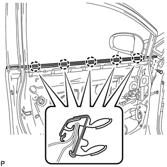
(b) Install the clip.
2. INSTALL FRONT DOOR GLASS RUN
.gif)
3. INSTALL FRONT DOOR GLASS SUB-ASSEMBLY
4. INSTALL FRONT DOOR SERVICE HOLE COVER
5. INSTALL FRONT NO. 1 SPEAKER ASSEMBLY
6. INSTALL DOOR SIDE AIRBAG SENSOR
7. INSTALL FRONT DOOR INSIDE HANDLE SUB-ASSEMBLY
8. INSTALL FRONT DOOR TRIM BOARD SUB-ASSEMBLY
9. INSTALL COURTESY LIGHT ASSEMBLY
10. INSTALL POWER WINDOW REGULATOR MASTER SWITCH ASSEMBLY WITH FRONT DOOR ARMREST BASE PANEL (for Driver Side)
11. INSTALL POWER WINDOW REGULATOR SWITCH ASSEMBLY WITH FRONT DOOR ARMREST BASE PANEL (for Front Passenger Side)
12. INSTALL FRONT DOOR INSIDE HANDLE BEZEL PLUG
13. CONNECT CABLE TO NEGATIVE BATTERY TERMINAL
NOTICE:
When disconnecting the cable, some systems need to be initialized after the cable
is reconnected (See page ).
14. INSPECT SRS WARNING LIGHT
(See page )
15. INITIALIZE POWER WINDOW CONTROL SYSTEM
(See page )
 Components
COMPONENTS
ILLUSTRATION
ILLUSTRATION
...
 Removal
REMOVAL
PROCEDURE
1. DISCONNECT CABLE FROM NEGATIVE BATTERY TERMINAL
CAUTION:
Wait at least 90 seconds after disconnecting the cable from the negative (-)
battery terminal to disable the SRS sys ...
Other materials about Toyota Venza:
ABS Control System Malfunction (43)
DESCRIPTION
This DTC is output when the VSC system detects a malfunction in the ABS control
system.
DTC Code
DTC Detection Condition
Trouble Area
43
Malfunction in the ABS control system.
...
Power Back Door Warning System does not Operate
DESCRIPTION
When the power back door warning system does not operate, one of the following
may be malfunctioning: 1) power back door warning buzzer circuit, 2) wireless door
lock control system or 3) power back door ECU.
WIRING DIAGRAM
CAUTION / NOTIC ...
Evaporative Emission System Leak Detection Reference Orifice Low Flow (P043E,P043F,P2401,P2402,P2419)
DTC SUMMARY
DTC No.
Monitoring Item
Malfunction Detection Condition
Trouble Area
Detection Timing
Detection Logic
P043E
Reference orifice clogged
P043E, P ...

0.1153